STLINK Programming and Reconfigurable Kit (SPARK)
Overview
The SPARK board is a breakout and development interface built around the STLINK-V3MODS debugging module. While the STLINK-V3MODS provides powerful debugging and programming capabilities for STM32 development, the raw module is not particularly convenient to use directly on a workbench or during board bring-up.
SPARK was designed to turn the STLINK-V3MODS into a practical development tool by exposing its key interfaces through accessible connectors and providing a stable platform for repeated use in embedded development workflows. The board breaks out debugging and communication interfaces commonly used during firmware development, making it easier to connect to target systems without custom wiring or adapter boards.
The goal of the project was to create a simple, reliable interface that could be used for firmware debugging, board bring-up, and embedded systems development, while remaining easy to reproduce and integrate into other projects. The result is a compact hardware tool that bridges the gap between ST’s modular debugger and the practical needs of day-to-day embedded engineering work.
Problem
The STLINK-V3MODS is a powerful debugging interface for STM32 development, but in its raw module form it is difficult to integrate into test benches and development setups.
The module exposes a high-density connector and assumes a carrier board, which adds friction when using it for rapid prototyping, board bring-up, or firmware debugging.
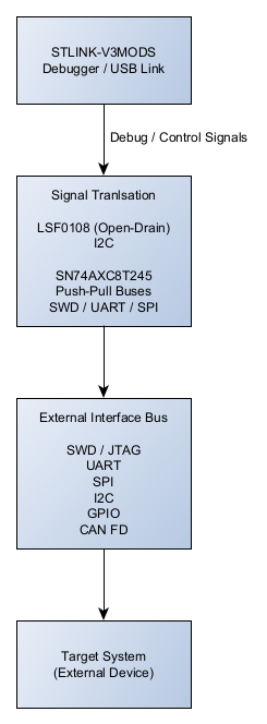
System Architecture
Core structure
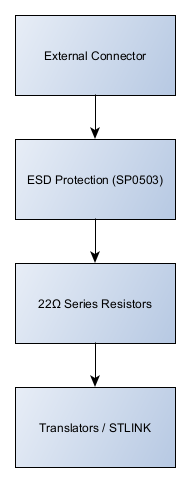
Protection layer
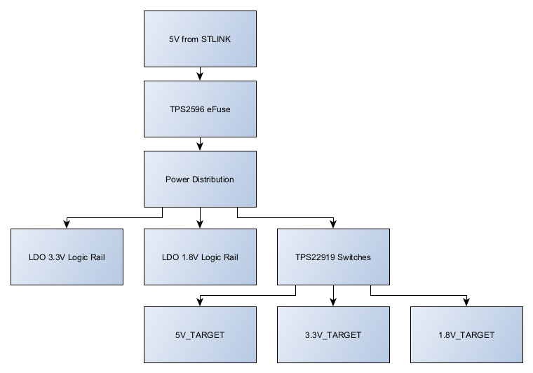
Supporting systems
Interfaces
SPARK exposes the key interfaces of the STLINK-V3MODS module in a form that is easier to access during development and board bring-up.
-
Debug Interface:
Standard SWD (Serial Wire Debug) signals are broken out to headers, allowing the debugger to program and control the target microcontroller during firmware development and troubleshooting. -
Serial Communication Interface:
The STLINK Virtual COM Port (UART) is routed to accessible connectors so the host computer can communicate with the target system for logging, console interaction, and runtime diagnostics. -
Target Connection Interface:
Target connections are provided through clearly organized header pins, allowing quick connection to embedded hardware during firmware development, board validation, and debugging workflows.
Hardware Architecture Highlights
SPARK was designed as a robust interface platform for the STLINK-V3MODS debugger with emphasis on signal integrity, electrical protection, and reliable target interaction.
Key architectural features include:
- Hardened signal path between debugger and external connectors
- Hybrid level translation architecture tailored to bus behavior
- Switchable target power rails with default-safe startup behavior
- Per-line ESD protection and series impedance on external signals
- 4-layer PCB with extensive ground stitching for improved signal integrity
Key Design Decisions
-
Decision: Use the STLINK-V3MODS module as the core debugging engine.
Rationale: This preserves full compatibility with the existing ST ecosystem (STM32CubeIDE, OpenOCD, and other standard tooling) while avoiding the need to design or maintain custom debugging firmware. -
Decision: Focus the board on clean signal breakout rather than adding active circuitry.
Rationale: Keeping the board electrically simple improves reliability and makes the tool easier to reproduce, troubleshoot, and use during early hardware bring-up. -
Decision: Expose commonly used development interfaces through accessible headers.
Rationale: During firmware development and board validation, engineers frequently need quick access to SWD and UART connections. Providing direct access reduces wiring complexity and speeds up debugging workflows. -
Decision: Prioritize bench usability and repeated use.
Rationale: The board is intended to function as a practical development tool during day-to-day embedded work, so connector placement and layout were chosen to make connections straightforward during testing and board bring-up.
Implementation
-
Designed a compact breakout PCB that integrates the STLINK-V3MODS module and routes its primary debugging interfaces to accessible connectors.
-
Routed the SWD debug signals (SWDIO, SWCLK, NRST, GND, and target reference voltage) to standard header pins to simplify connection to STM32 and other ARM-based target systems during firmware development and board bring-up.
-
Exposed the STLINK Virtual COM Port (UART) through dedicated header pins, allowing the host computer to communicate with the target system for logging, debugging output, and console interaction.
-
Laid out the board to prioritize signal clarity and physical accessibility, with connectors positioned along the board edge to make repeated connections easier during bench testing.
-
Prototyped the design using standard PCB fabrication and assembly workflows and validated it during embedded development activities requiring frequent programming and debugging of STM32-based systems.
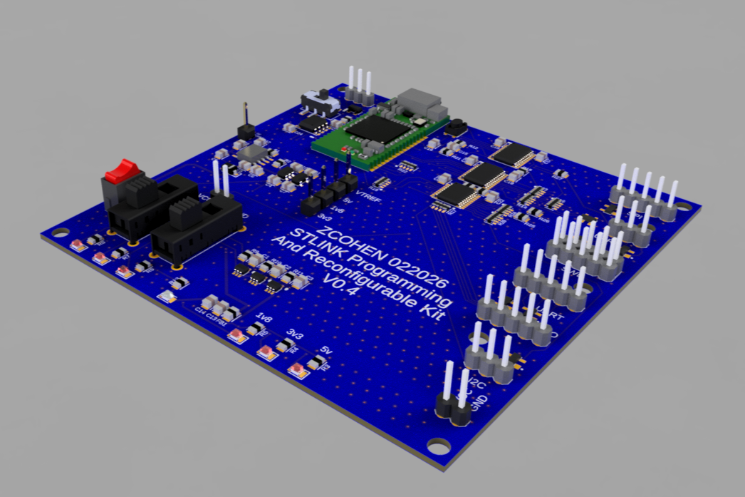
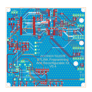
Artifacts
Board layout
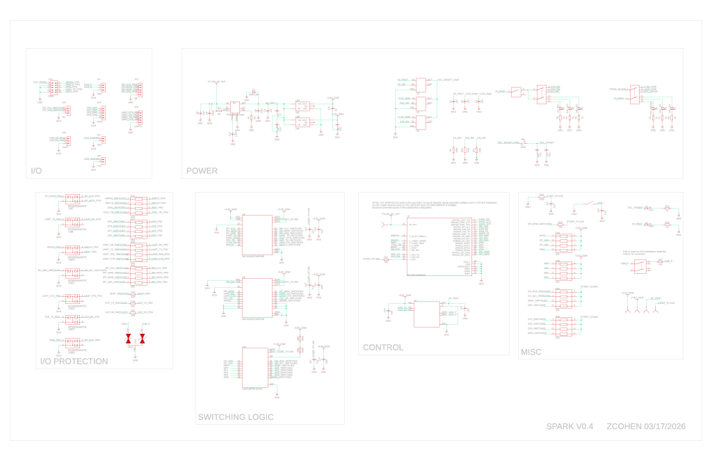
Schematic
Lessons Learned
-
Use standard tools whenever possible.
Building around the STLINK-V3MODS allowed the project to leverage ST’s existing debug ecosystem instead of reinventing the probe itself. This significantly reduced development complexity while maintaining compatibility with common STM32 development workflows. -
Hardware tools benefit from simplicity.
Keeping the board electrically simple made it easier to prototype, assemble, and troubleshoot. Avoiding unnecessary active circuitry improved reliability and ensured the board behaves predictably during debugging. -
Bench usability matters more than expected.
Connector placement, clear signal breakout, and physical accessibility turned out to be just as important as the electrical design. Small layout decisions can have a large impact on how comfortable a tool is to use during repeated firmware development and board bring-up. -
Design tools for real workflows.
The most valuable feature of the board is not additional functionality, but reducing friction during everyday debugging tasks. Designing tools around actual development habits makes them far more useful than purely theoretical feature sets.
| Project Status: Prototype Deployment | Timeline: May 2025 - Present |
| ← Previous: Autonomous Surfer Fleet | Next Project: Fusion Blocks → |