Fusion System Blocks
Overview
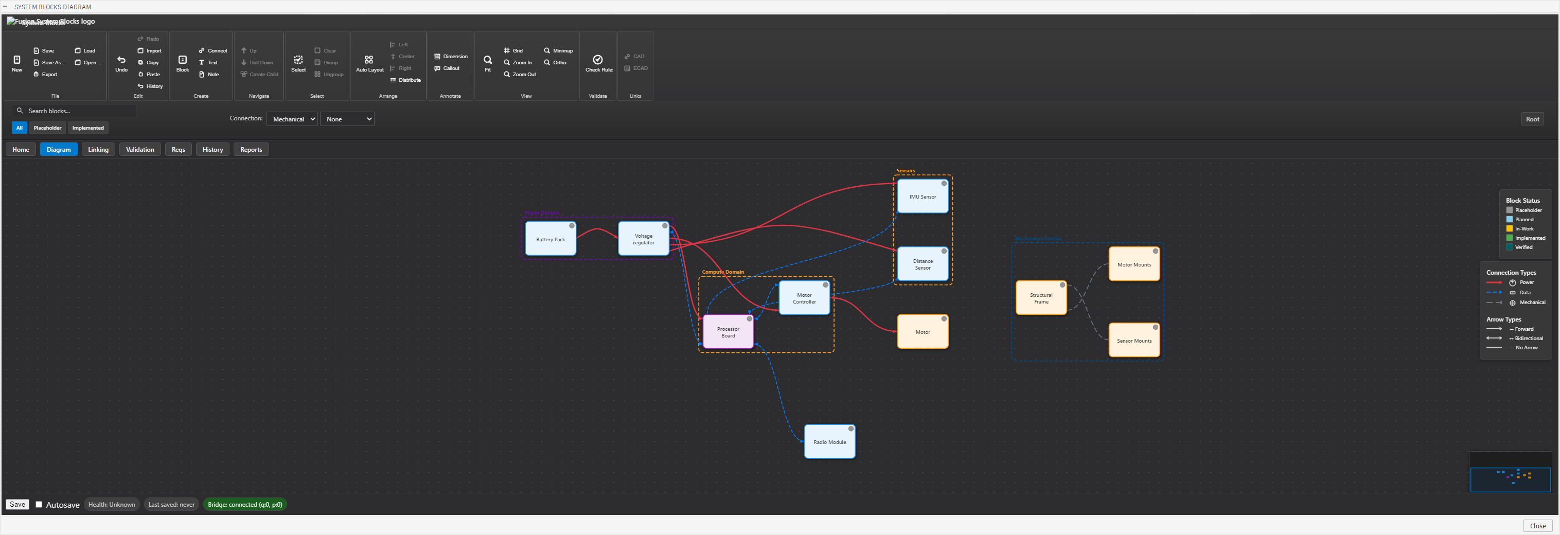
Fusion System Blocks is a systems-documentation workflow built around Autodesk Fusion and lightweight diagramming tools. It provides a structured way to represent system architecture, subsystem boundaries, and interface relationships during multidisciplinary engineering projects.
The goal of the framework is to keep system documentation synchronized with engineering work as mechanical, electrical, and firmware designs evolve. By defining subsystem blocks and explicitly documenting interfaces between them, the workflow creates a shared visual language that supports design discussions, integration planning, and technical reviews.
Rather than serving as a traditional requirements document, Fusion System Blocks acts as a living system map that evolves alongside the design.
The workflow was created to bridge the gap between high-level architecture discussions and detailed engineering implementation. By maintaining a visual map of subsystem relationships and interfaces, teams can reason about system behavior before hardware or software changes are made.
Problem
Multidisciplinary engineering projects often struggle with traceability between mechanical structures, electronics, firmware, and system behavior. Architecture decisions are frequently captured in scattered notes, whiteboard sketches, or discipline-specific documents that are difficult for other team members to interpret.
As systems grow in complexity, the lack of a shared architectural view can lead to:
- unclear subsystem responsibilities
- poorly defined interfaces between disciplines
- integration challenges late in development
- inconsistent documentation across teams
Fusion System Blocks was developed to provide a lightweight architectural framework that keeps subsystem relationships and interface definitions visible throughout the design process.
System Architecture
The framework organizes system knowledge through several layers:
- System Context – defines the overall mission and boundaries of the system.
- System Architecture – establishes the high-level structure and major subsystems.
- Subsystem Blocks – represent functional elements such as electronics, mechanical structures, and control systems.
- Interface Definitions – document the electrical, mechanical, and software connections between subsystems.
- Linked Documentation – connects diagrams to deeper technical notes, design files, and development artifacts.
This layered approach allows architecture discussions to remain aligned across disciplines while maintaining traceability to detailed engineering documentation.
Key Design Decisions
-
Decision: Use top-down system decomposition.
Rationale: Starting from system context and progressively defining subsystems ensures that architecture decisions remain visible to all disciplines during development. -
Decision: Represent subsystems as modular system blocks.
Rationale: Block-level abstraction makes complex systems easier to reason about while keeping interface boundaries explicit. -
Decision: Separate interface definitions from subsystem internals.
Rationale: Clearly defined interfaces reduce integration ambiguity and allow mechanical, electrical, and firmware teams to evolve subsystems independently. -
Decision: Store documentation alongside engineering artifacts in version control.
Rationale: Architecture diagrams and notes evolve with the project and remain synchronized with design revisions.
Implementation
The workflow combines visual system diagrams with repository-based documentation.
Key elements include:
- System block diagram templates used to map subsystem relationships and architecture layers.
- Interface documentation patterns describing electrical, mechanical, and communication boundaries between subsystems.
- Linked documentation structure connecting diagrams to markdown design notes, CAD models, and firmware repositories.
- Version-controlled architecture artifacts that evolve with the engineering project rather than existing as static documentation.
This approach allows architecture discussions, design reviews, and implementation work to remain connected throughout development.
Where This Workflow Is Used
Fusion System Blocks is used to structure architecture discussions and documentation for several engineering projects, including:
- SENTRY turret platform – defining subsystem boundaries between the control electronics, pan/tilt mechanics, safety logic, and sensor interfaces.
- SPARK debugging interface – mapping the relationship between the STLINK-V3MODS module, signal translation architecture, protection circuitry, and external debug interfaces.
- Autonomous vessel control systems – representing distributed subsystems including onboard controllers, power systems, communication links, and sensor inputs.
Using the same architectural structure across projects helps maintain consistency in how systems are discussed, reviewed, and documented.
Lessons Learned
-
Architecture documentation must stay lightweight.
If diagrams require too much effort to maintain, they quickly fall out of sync with the design. -
Explicit interface boundaries simplify integration.
Defining electrical, mechanical, and data interfaces early reduces ambiguity during system integration. -
Visual system maps improve technical communication.
Shared diagrams provide a common vocabulary that helps engineers from different disciplines understand the system more quickly. -
Living documentation supports better design reviews.
When architecture diagrams evolve alongside the project, they become valuable tools for planning, troubleshooting, and onboarding new collaborators.
| Project Status: Public Release | Timeline: 2025–2026 |
| ← Previous: SPARK Programming Board | Back to Projects → |