Sentry V3: Production Embedded Actuation System

Overview
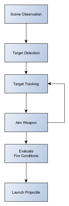
SENTRY V3 is an embedded electromechanical platform that integrates sensing, actuation, and control for a pan-tilt robotic turret system. The platform combines custom motor control electronics, sensor interfaces, and embedded firmware to coordinate flywheel propulsion, ammunition feeding, and two-axis positioning. The design supports modular expansion and allows higher-level compute systems to command the platform while the embedded controller handles real-time motor control and safety behavior.
Problem
Earlier versions of the platform relied on ad-hoc wiring and distributed control logic, which made integration, testing, and debugging difficult. The V3 design consolidates motor control, sensor interfaces, and safety handling into a dedicated embedded controller, creating a more maintainable architecture for experimentation and development.
System Architecture
Hardware Design
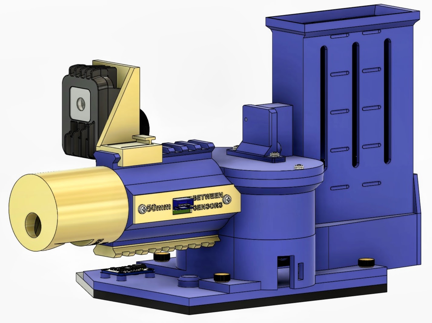
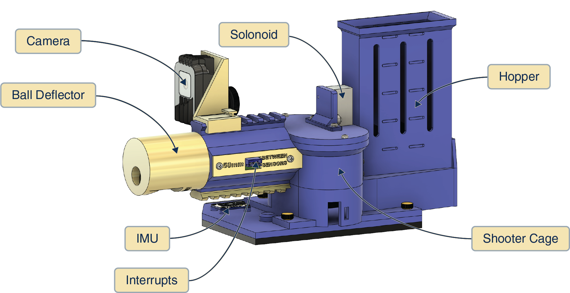
The mechanical and electrical design of SENTRY V3 was developed together so the control board, drivetrain, sensor placement, and service access all supported reliable integration. The platform layout emphasizes subsystem separation, maintainable wiring, and clear mechanical paths for actuation and feed components.
CAD assembly overview
Labeled subsystem view
Interfaces
- Power interfaces: Single DC input supplying the platform, with onboard regulation providing local 5 V and 3.3 V rails for logic, sensors, and motor drivers.
- Data interfaces: I²C bus for onboard sensors and analog expansion, along with USB or serial communication to an external host computer used for higher-level control and perception.
- Control interfaces: PWM and digital GPIO used for motor drivers and actuators, with additional GPIO inputs for system triggers and safety control.
Key Design Decisions
- Decision: Separate high-level control from real-time motor control. Rationale: Allow external compute systems to handle perception and targeting while the embedded controller manages timing-critical motor control and safety behavior.
- Decision: Use a microcontroller-based control board (RP2040) for actuator coordination. Rationale: Provide deterministic timing for motor control, sensor polling, and actuator sequencing without relying on a general-purpose host computer.
- Decision: Place sensors and auxiliary devices on a shared I²C bus. Rationale: Reduce wiring complexity and allow new sensors to be added without redesigning the control architecture.
- Decision: Use discrete motor drivers for pan, tilt, flywheel, and feed mechanisms. Rationale: Allow each subsystem to be controlled and tuned independently while simplifying debugging during bring-up.
- Decision: Integrate current monitoring on the flywheel drive. Rationale: Detect projectile events through current spikes, enabling reliable shot counting without additional sensors.
Implementation
- Custom control PCB integrating motor drivers, sensor interfaces, and power regulation for turret subsystems.
- Embedded firmware running on the RP2040 that coordinates flywheel spin-up, ammunition feed control, and pan–tilt positioning.
- I²C sensor integration for orientation and system monitoring, with current sensing used to detect projectile events during firing.
- Integration with an external compute platform responsible for vision processing and target selection while the embedded controller manages real-time actuation.
- Bench testing and bring-up performed using logic analysis, current monitoring, and iterative firmware tuning.
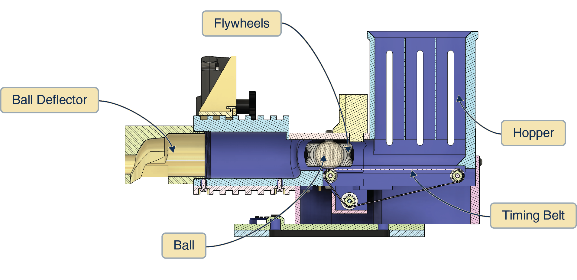
Cross-section view
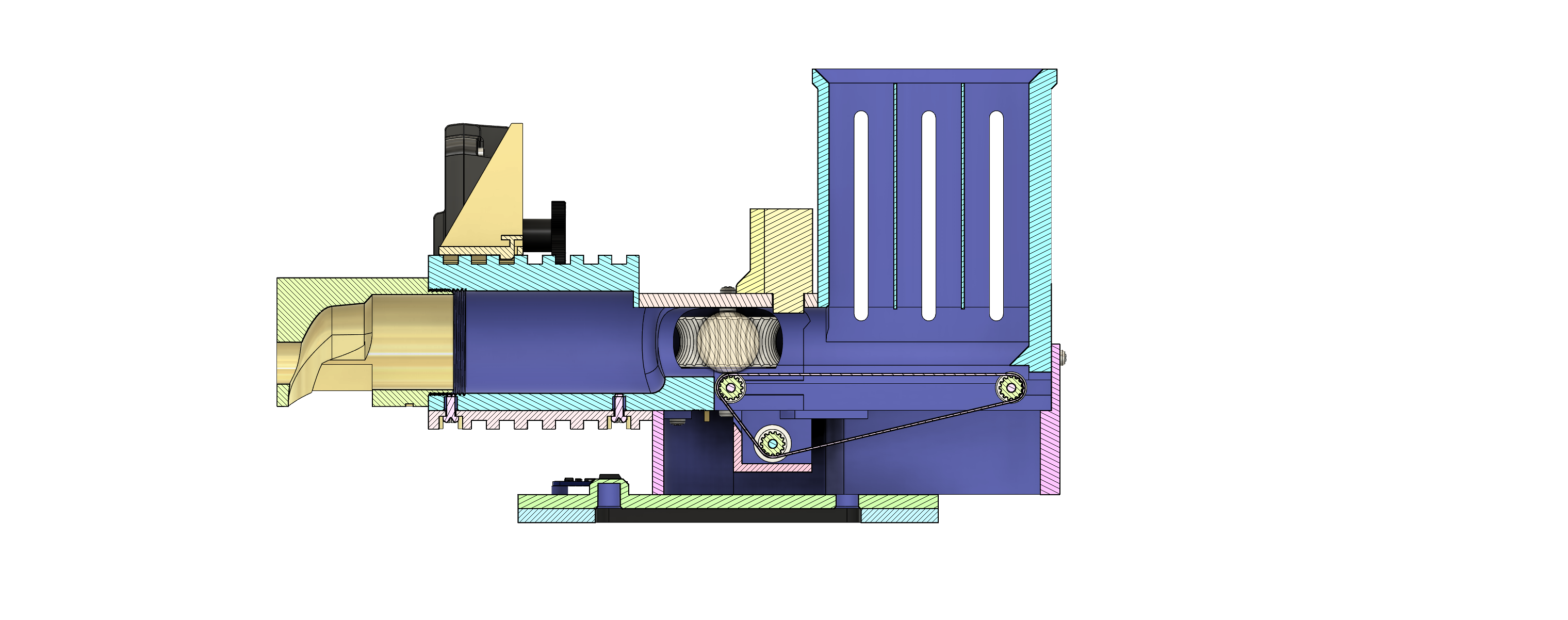
Labeled cross-section
Artifacts
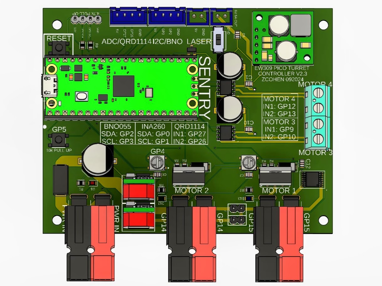
Control board integration
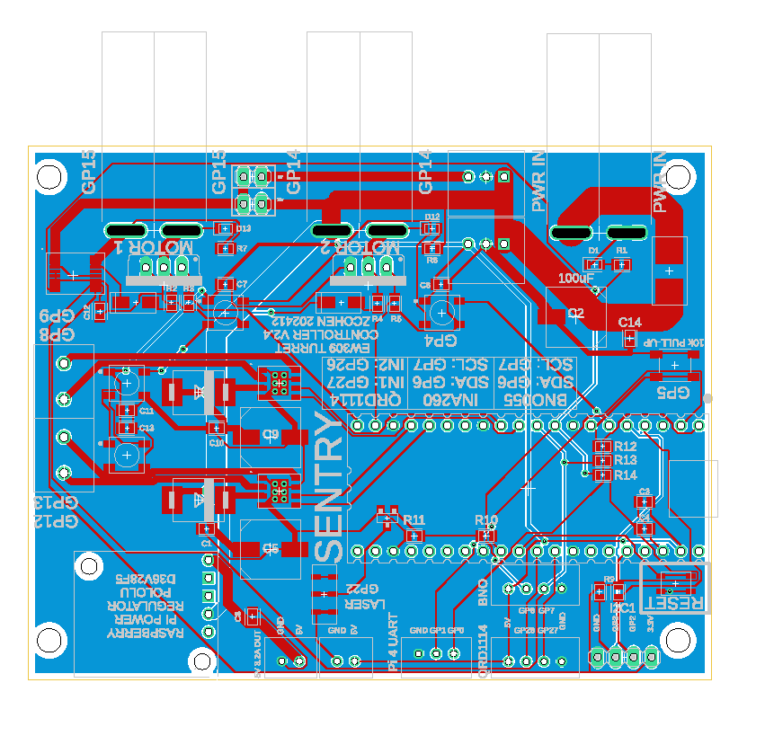
PCB layout
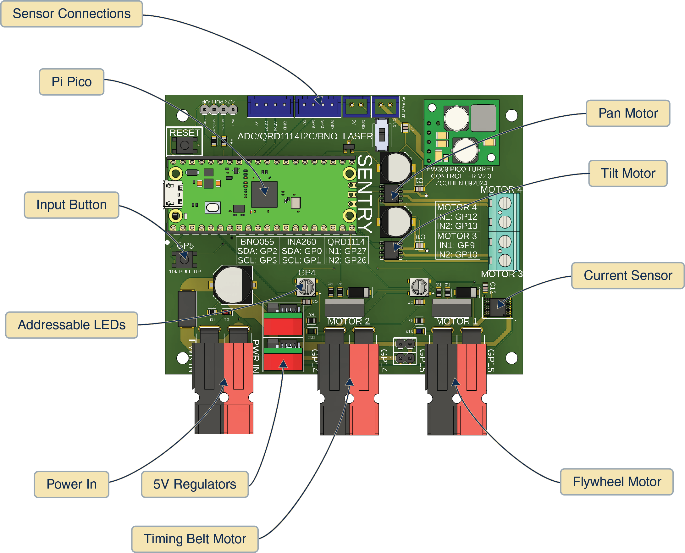
Labeled PCB
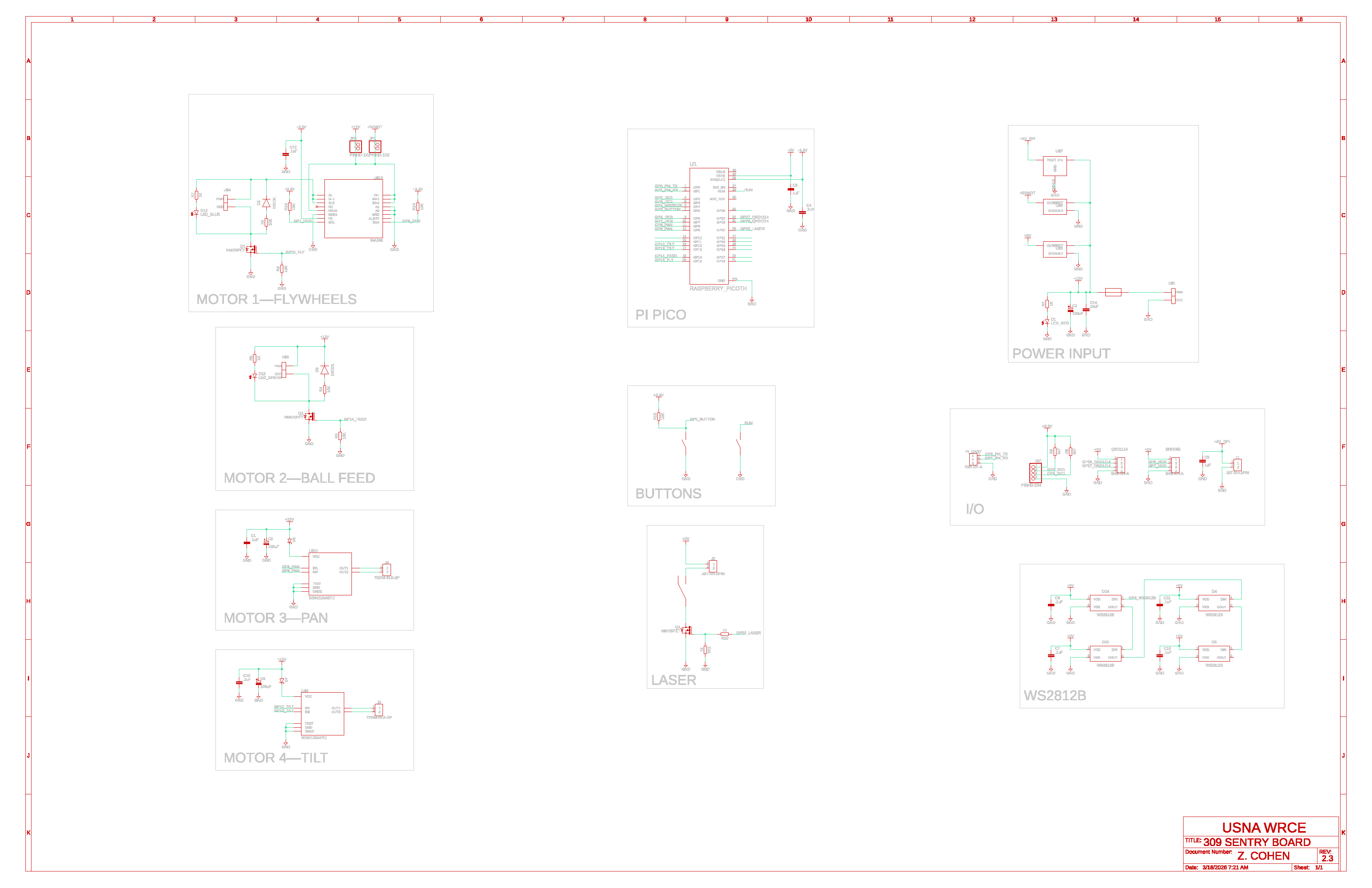
Electronics schematic
Lessons Learned
- Separating high-level control from real-time actuation simplifies system behavior and makes debugging significantly easier.
- Current sensing can serve as a reliable proxy for mechanical events when adding dedicated sensors would increase complexity.
- Integrating multiple motor-driven subsystems requires careful sequencing and state management to prevent unexpected interactions between actuators.
- Early bring-up instrumentation (current monitoring, logic analysis, and serial diagnostics) greatly reduces iteration time during firmware development.
- Designing the control board with spare interfaces and expansion capability makes it easier to add sensors and experiment with new control strategies.
SENTRY V4 — Next Steps
SENTRY V4 represents a major architectural redesign of the SENTRY platform.
Rather than iterating on the previous PCB, the system is being re-architected from first principles to improve reliability, safety, and educational usability.
The goal of V4 is to transform SENTRY from a prototype control stack into a robust robotics platform that cleanly separates perception, orchestration, control, and safety.
1. Establish System Architecture
The first step is defining the complete system architecture before beginning schematic or PCB work.
Key architectural elements:
- Vision Layer — Oak-D stereo camera performing onboard depth and neural inference
- Compute Layer — Raspberry Pi Compute Module 5 orchestrating perception and student code
- Control Layer — RP-series MCU (RP2040/RP2350 class) performing deterministic real-time control
- Safety Layer — dedicated safety supervisor MCU enforcing hardware-level safety constraints
Responsibilities are intentionally separated so that:
- Linux cannot directly control actuators
- student firmware cannot bypass safety enforcement
- perception and real-time control operate independently
This layered architecture significantly improves fault containment and system reliability.
2. Design Independent Safety Supervisor
A new hardware safety supervisor will be added to the system.
This subsystem is implemented using a small microcontroller (ATtiny-class device) whose only responsibility is safety enforcement.
The safety supervisor will monitor:
- E-stop input
- pan and tilt limit switches
- RP controller heartbeat
- actuator runtime limits
- system power brownout
- main input overcurrent
The safety controller implements a three-level fault model:
Level 2 — Warning
- status LED / telemetry
- no immediate shutdown
Level 1 — Motion Inhibit
- actuator driver enables disabled
- system remains powered for debugging
Level 0 — Hard Shutdown
- safety relay opens
- actuator power rail disconnected
- manual reset required
This layered safety approach allows the platform to remain usable during minor faults while still enforcing strict safety guarantees.
3. Define Power Architecture
The V4 board will introduce a clear separation between logic and actuation power domains.
The primary power structure will include:
- protected system power input
- actuator power rail (relay controlled)
- 5V compute rail for the CM5
- 3.3V logic rail for MCU and sensors
Protection features will include:
- input overcurrent detection
- brownout detection
- power sequencing
- relay-based motion power cutoff
Separating these domains improves electrical stability and reduces noise coupling between motors and compute systems.
4. Define Communication Interfaces
Communication paths will be explicitly defined between system layers.
Primary internal link:
- UART between CM5 and RP MCU
- structured command protocol
- heartbeat monitoring
- telemetry reporting
External access paths:
- USB device interface to the MCU for beginner firmware development
- USB gadget or network access to the CM5 for advanced Linux-based control
- USB host connection between CM5 and Oak-D camera
These pathways allow the system to support both introductory embedded learning and advanced robotics experimentation.
5. Develop PCB Floorplan
Before schematic entry, the physical PCB layout will be planned around four functional zones:
- Compute Domain (CM5 and high-speed interfaces)
- Control Domain (RP MCU and sensors)
- Safety & Power Supervision
- Actuation Domain (motor drivers and MOSFETs)
Separating these zones simplifies routing and minimizes electrical interference between high-current motor systems and digital compute hardware.
6. Begin Schematic Capture
Once the architecture, power topology, and floorplan are finalized, schematic development will begin.
Key schematic areas include:
- compute module carrier circuitry
- MCU control subsystem
- safety supervisor logic
- power distribution and protection
- motor driver interfaces
- sensor expansion headers
The schematic will be developed with strong emphasis on clear domain boundaries and debuggability.
7. PCB Stackup and Layout
Because the system integrates high-speed compute and power electronics, the board will likely use a 6-layer stackup to maintain signal integrity and provide solid ground reference planes.
Typical structure:
- Signal
- Ground
- Signal
- Power
- Ground
- Signal
This provides clean return paths for digital signals while isolating actuator switching currents.
8. Open Hardware Documentation
The final step will be publishing the full system documentation including:
- architecture diagrams
- block diagrams
- safety model
- communication protocol
- schematic and PCB files
The intent is for SENTRY V4 to function as a fully documented open robotics control platform that others can study, modify, and build upon.
Long-Term Vision
While originally developed for the SENTRY turret system, the V4 architecture is designed to be reusable as a general robotics control motherboard combining:
- onboard perception
- deterministic motion control
- layered safety supervision
- clean power and interface architecture
This approach allows the platform to scale beyond a single application while remaining approachable for students and makers.
| Project Status: Production Deployment | Timeline: January 2024 - December 2025 |
| ← Back to Projects | Next Project: Surfer Fleet → |