Cable Shielding, Grounding, and Bonding
Shielding is easy to specify badly: buy a shielded cable, connect its drain to something called ground, and hope. The missing information is which interference you are controlling, where its current will flow, and what the complete interface does at those frequencies.
This page expands Connector Anatomy §5.7. It covers cable shields and connector/enclosure bonds. It is a design guide, not a replacement for the equipment's installation manual or a complete protective-earthing design.
Follow the equipment manufacturer's cable and bonding instructions first. For a custom interface, identify the noise source, coupling path, receiver, cable route, and bonding network before choosing the shield arrangement. There is no universal instruction to bond every shield at one end or every shield at both ends.
1. Four functions that a “ground” label can hide
| Function | Purpose | What to define |
|---|---|---|
| Power return | Carries normal load current back to its source | Current, voltage drop, conductor/contact sizing, disconnection and backfeed paths |
| Signal reference / return | Establishes the signal's voltage reference and, where applicable, carries signal return current | Interface circuit, common-mode limits, reference conductor, intentional joins and isolation |
| Shield / chassis bond | Controls EMC currents at a cable or enclosure boundary | Physical termination, frequency range, conductive interfaces, bond locations |
| Protective earth / protective bonding | Performs a required electrical-safety function | Applicable equipment and installation requirements, fault path, continuity and conductor sizing |
These functions can share a connection by design; matching net names do not establish that design. TI's chassis-ground discussion separates enclosure/connector-shield treatment from signal circuitry.1 NI's grounding guide separately addresses equipment and facility grounding requirements.2

Independent role sketches, not a complete wiring schematic. Protective-earth and fault-current paths are not shown. Record every intended connection between these functions in the ICD and schematic.
An important exception is coax: its outer conductor is normally the signal return as well as a shield. Lifting it using a shielded-twisted-pair rule can break the interface. ADI's coax examples distinguish a differential receiver from a conventional single-ended receiver; the circuit determines the permissible connection.3 See the RF/GPS/radio path.
2. What shielding helps, and what it does not fix
Think in terms of source → coupling path → affected circuit. A nearby wire with rapidly changing voltage couples differently from a high-current loop or a shared return conductor.4
| Mechanism | Useful controls | Shielding limit |
|---|---|---|
| Electric-field / capacitive coupling | Separation, lower source impedance where appropriate, a suitably bonded conductive shield | A floating or poorly connected screen may fail to control the coupling |
| Magnetic-field / inductive coupling | Keep each circuit's conductors close, twist suitable pairs, reduce loop area, separate from the source | Ordinary thin copper/aluminum screening is a poor remedy for low-frequency magnetic pickup |
| Conducted / common-impedance coupling | Correct return routing, power filtering, reduce shared impedance, reconsider architecture | A cable screen cannot remove a voltage drop already created in a shared supply/return path |
| Radiated interference and common-mode cable currents | Cable/enclosure shielding, suitable bonds and entry filtering, interface balance | The assembled cable, connector, enclosure and circuit must work together |
Phoenix Contact explains electric, magnetic and radiated coupling; ADI also treats shared-impedance coupling.54 The practical inference is to match the mitigation to the path, rather than treating a screen as a cure for every noise symptom.

Mechanisms and possible controls, not predicted attenuation. The sketches omit complete supply and return circuits and are not to scale.
Twisting and shielding are complementary. Pair the two conductors that belong to the same circuit: a signal and its return, or the two members of a differential pair. A shield around separated conductors does not make their enclosed loop area small.5 Conversely, a differential input still has finite rejection and a limited common-mode range; it is not immune to every disturbance.67
Also distinguish signal bandwidth from interference bandwidth. A slowly changing sensor can be disturbed by RF that is rectified into an apparent low-frequency error. NI describes this mechanism for analog acquisition.6 Do not choose the bond solely from the sensor's sample rate or a bus's nominal bit rate. Cable length relative to interference wavelength also matters; there is no universal frequency at which every cable should change bonding arrangements.5
3. When to specify a shielded cable
Use the equipment's specified cable when it is part of the interface or installation requirement. For a custom design, document the case for shielding:
- A sensitive analog measurement runs near switching converters, drives, transmitters, or long external wiring.
- A cable is a likely emission path from your equipment, even if the receiver's data looks clean.
- An external interface must meet a defined EMC environment and test requirement.
- The intended connector/cable system uses the shield as a functional conductor, as in coax.
An unshielded, correctly paired and routed cable may be suitable where the requirements and evidence support it. Shielding adds cable diameter, termination work, bond interfaces, and service constraints. Belden's Category-cable guidance recommends evaluating the equipment requirements and the installed cabling system, rather than assuming that a shielded cable alone is an upgrade.8
Before adding a screen, review source suppression, separation from power wiring, loop area, and return paths. Those controls remain necessary after shielding is added. Make the selection reviewable: required by manual, chosen for an identified mechanism, or still to be validated.
4. One end, both ends, or a hybrid bond
These are three different arrangements for a shield that is not the intended signal return. The drawing omits signal-reference and protective-earth connections; it does not authorize removing them.

Teal upper/lower lines represent one surrounding cable screen. These are alternative bond arrangements, not interchangeable recipes. The capacitor is an EMC component, never a substitute for a required protective-earth connection. Actual bond points, components, and cable ends come from the interface design.
One direct bond
A one-end arrangement can be appropriate for low-frequency electric-field pickup in a measurement system where the shield should not carry circulating low-frequency ground current. The unbonded end must be deliberately insulated from connector hardware and nearby metal.
Which end matters. NI's capacitive-coupling example uses a source-end connection; ADI's passive-RTD example connects at the conditioning/receiving end. Those are different circuit configurations, not a universal preference for the transmitting or receiving end.69
Check the sensor's case/earth connection, receiver input arrangement, bias-current path, and other cables. A shield that is nominally “open” can acquire an accidental bond through a backshell, mounting bracket, grounded sensor body, or adapter. One direct bond also leaves the far end without a deliberate RF bond; verify the actual interference environment.
Direct bonds at both ends
For many industrial EMC interfaces, both ends are bonded to the designated enclosure/chassis structures through broad, short connections. Use the drive manual's arrangement for a drive cable. Schneider specifically requires both-end bonding for Altivar shielded motor cables; SEW's cited installation guidance also specifies both ends while identifying limited exceptions for its system.1011
A ground-potential difference can drive current through this shield path. Address the equipment bonding network and permitted shield currents; do not make the shield the accidental equalizing conductor for inadequately bonded structures. SEW explicitly calls for appropriate equipotential bonding where the endpoint potentials differ.11
One direct bond plus a capacitive far-end bond
A designed hybrid arrangement can interrupt the direct DC/low-frequency shield loop while providing a capacitive RF connection. ADI shows sensor examples of this approach.9
It needs engineering: capacitance, voltage and transient ratings, leakage limits, applicable safety constraints, parasitic inductance, mechanical placement, and verification. A capacitor's ideal impedance is frequency-dependent; its mounting and leads also matter. Do not copy a capacitor value from an unrelated example or replace a mandated direct bond with one.
A shield floating at both ends
Do not leave a screen unconnected simply because the correct bond is unresolved. It is not a dependable default for electrostatic shielding. A driven guard or another deliberately engineered structure is a different circuit, with its own instructions and stability requirements.
5. A practical decision matrix
These are investigation starting points, not permissions to override product instructions.
| Interface / situation | Starting point | Decision still needed |
|---|---|---|
| Passive low-level sensor into a DAQ | Check the sensor/DAQ's one-end or hybrid arrangement | Grounded/floating source, input bias path, designated end, RF exposure |
| Shielded drive-to-motor cable | Follow the drive/motor manual; both-end broad bonds are commonly specified | Motor-frame and cabinet bonds, shield hardware, required PE, routing |
| Shielded Ethernet / serial data system | Use the approved cable, connector and bonding architecture | Shell continuity, chassis/reference arrangement, transceiver common-mode limits |
| Coax RF or single-ended coax measurement | Treat the outer conductor as part of the signal circuit | Receiver topology, impedance, intentional chassis connections |
| Equipment on different structures or supplies | Establish bonding and ground-potential requirements before deciding | Isolation, surge protection, shield current and safety paths; consider fiber |
Long runs and ground loops are architecture questions. TI shows how ground-potential difference and coupled noise can exceed an RS-485 receiver's common-mode capability, and how isolating both signal and transceiver power addresses that interface problem.7 Isolation does not make its parasitics, shield connections, surge environment, or protective bonding disappear. Define those separately.
6. Foil, braid, drain wire, and shield coverage
| Construction | What it means | What to verify |
|---|---|---|
| Foil | Conductive layer around conductors or pairs | Continuity/overlap, flex duty, prescribed termination |
| Braid | Woven conductive strands with openings | Coverage, material, flex life, compatible clamp/band |
| Foil plus braid | Both layers in one cable | How each layer participates in the specified termination |
| Individual pair screens | Separate shields around particular pairs | Pair identification, approved breakouts and shield connections |
| Overall screen | Shield around the cable's conductor bundle | External EMC performance; internal crosstalk still needs assessment |
| Drain wire | Conductor provided to contact/terminate a screen in suitable constructions | Its required connection, length and handling; it is not a surrounding screen |
Belden describes foil, braid, and overall versus pair screening.8 Construction and optical coverage are not an attenuation rating. Ask for the exact cable's shielding/transfer-impedance evidence, test configuration and frequency range. Do not infer high-frequency performance from “100% coverage,” a braid percentage, or a generic “EMI cable” label alone.
Use flex-rated cable where it moves. A shield that performs electrically when new but cracks, frets, or loosens in service is not a successful assembly. Cable OD, bend radius, environmental sealing, strain relief, and shielding hardware must fit the same selected cable.
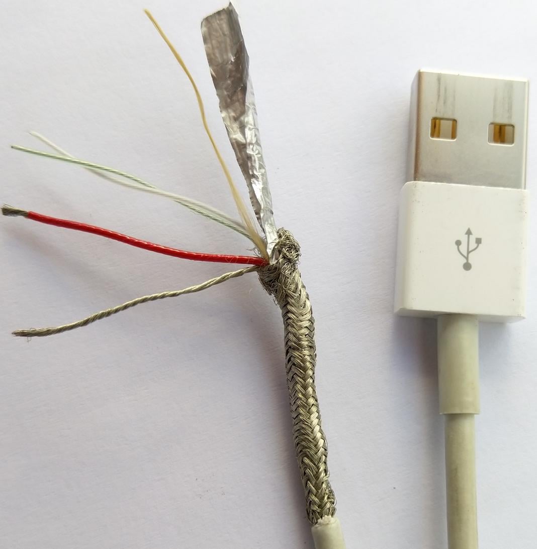
Real braid/foil cable construction. This cut specimen illustrates layers, not an approved shield termination, a generic USB pinout, or an attenuation rating. Photo: Anordal, CC BY-SA 4.0, via Wikimedia Commons. JPEG re-encoded; metadata stripped; original dimensions retained.
7. Carry the shield through the connector boundary
For an interface intended to have a circumferential enclosure bond, inspect the whole path:
Cable screen → termination hardware → backshell/shell or entry clamp → enclosure bond.

Local geometry comparison. A 360° termination describes the contact around the cable, not which cable ends are bonded.
A pigtail concentrates the connection into a wire and adds inductance; at increasing frequency, this can compromise the bond even when DC continuity is good. Glenair describes the asymmetrical current path and exposed conductor length associated with pigtail/drain-wire terminations.12 A drain-wire connection can still be the specified preparation for a particular low-frequency interface. The error is assuming that it gives the same broadband bond as the intended circumferential termination.
Check these physical details:
- Entry location: terminate at the intended enclosure boundary; avoid a long unshielded breakout routed past sensitive circuitry.
- Conductive interfaces: verify actual shell, backshell, mating-shell and panel continuity. Paint, insulating finishes, loose hardware, or corrosion can interrupt a bond.
- Plastic connectors: a cable screen cannot bond through insulating housing material. Detail an external shield clamp or another approved termination; the selection packet illustrates external clamps.
- Adapters and bulkheads: include every intermediate shield joint, not just the two endpoint connectors.
- Mechanical control: the shield termination is not automatically adequate strain relief. Define restraint and seal requirements separately.
TI's connector/chassis examples and Phoenix Contact's cabinet-entry guidance illustrate treating the enclosure bond as a physical EMC interface.113 A metal shell, an IP rating, and a continuity beep do not by themselves establish a shielding performance specification.
8. Worked decisions
A remote RTD beside a motor installation
Identify the RTD/conditioning circuit, whether the sensor case is grounded, input requirements, and the interference environment. Check the manufacturer's designated one-end or hybrid arrangement. Keep the measurement conductors paired and route away from motor power wiring. The motor cable's both-end requirement is not automatically the RTD cable's requirement. Record RF immunity as well as low-frequency measurement error; validate with the drive operating.
A removable module with a plastic signal connector
Use the defined field-I/O reference conductor and isolation architecture. If the proposed shield bond is through separate entry clamps, make those clamps, their chassis bonds, and their service disconnection part of the drawing and BOM. Neither a spare “GND” pin nor the shield silently becomes a second module power return. See the worked selection packet.
Two cabinets with a suspected potential difference
Do not start by lifting a shield or a required safety connection. Identify the bonding installation, common-mode voltage, current paths and fault exposure. Evaluate a suitable isolated interface or fiber where necessary. Test the selected architecture with all normally connected equipment present; a USB cable or bench instrument can change the path being evaluated.
These are engineering review sequences, not released wiring designs.
9. Troubleshooting without changing five things at once
- Define the symptom and acceptance limit. Record measurement error, resets, packet failures or emissions, and the operating state that triggers them.
- Map connections. Include power returns, signal references, shields, cases, PE, test instruments and service cables. Identify intended and accidental bonds.
- Look for the coupling path. Change routing or separation under controlled conditions; compare motor/drive states, loads and radios. Keep the approved safety connections intact.
- Inspect the physical boundary. Check shield breakouts, shell joints, panel finishes, clamp engagement and damaged cable. Compare against the assembly instructions.
- Measure with an appropriate method. A DC bond measurement can find an open or poor joint; it cannot establish RF bond impedance.13 Use suitable probes/instruments without creating a new return path or short through instrument ground.
- Change one justified feature and repeat. Record the configuration and result. A quiet bench test does not replace the applicable installed-system EMC verification.
Never disconnect required protective earth to troubleshoot noise. A screen or drain is not a substitute for a protective bonding conductor unless the exact equipment and applicable safety design explicitly establish that function.2
10. What belongs on the released drawing
Use the ICD, cable drawing, and qualification plan to capture:
- Cable P/N, pair assignments, screen construction, flex/environmental duty and dimensional limits.
- Shield bond point and method at each end and at every intermediate interface; identify any deliberately insulated end.
- Exact shell, backshell, clamp, band, gasket and finish requirements; controlled assembly instructions and inspection criteria.
- Any drain-wire preparation and routing, or capacitive connection with complete component/rating details.
- Signal references, power returns, PE/protective bonds, isolation boundaries and all intended joins.
- The interference mechanism, frequency range, manufacturer requirement or design rationale, acceptance limits and verification evidence.
- Service-disconnection behavior, reassembly checks and how unintended bonds are prevented.
“Shielded cable; ground shield” is not enough information to manufacture or review that interface.
Sources and scope
Sources were checked on 2026-10-05. Manufacturer examples establish their stated configurations; they do not make this page a verified design for an unspecified assembly. The decision matrix, worked reviews and troubleshooting sequence are engineering judgment. Source scope and diagram dependencies are recorded in Source Notes.