USB-C Power for Hobby Projects
USB-C is the best project power inlet most hobby electronics has ever had: one reversible jack, a specified 10,000-cycle mating life,1 a universe of cheap supplies, and a negotiated ladder from 5 V bench power to 240 W. It is also the first power connector most makers meet that requires attachment detection before power — a compliant Type-C source leaves VBUS at its safe-zero state until it detects the sink's correct CC termination.2 Almost every "my board won't power up over USB-C" story on earth is one of the handful of rules on this page, and the most famous victim was the Raspberry Pi 4.
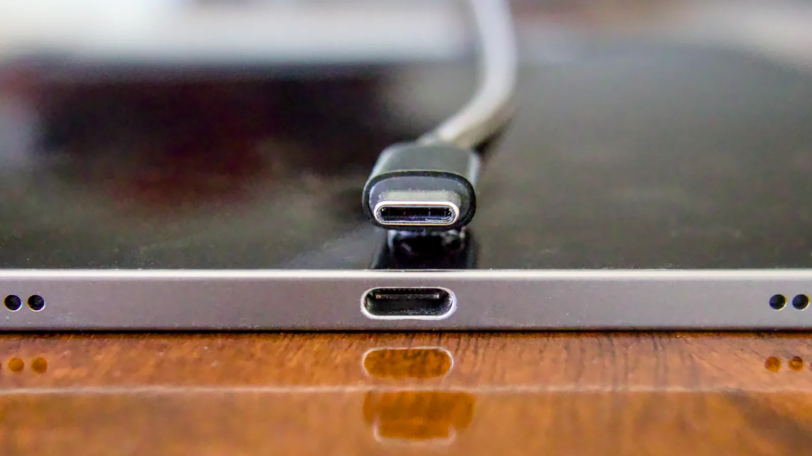
The reversible interface in its actual form: a USB-C plug and receptacle. The symmetry makes orientation easy; it does not make the port mechanically rugged, sealed, or electrically self-configuring. Photo: Wikideas1, CC0 1.0, via Wikimedia Commons; resized for web delivery.
1. The deal: power is negotiated, not assumed
A barrel jack is a wire from a wall adapter; USB-C is a protocol with a connector attached. Three escalating levels:
- Legacy default — an A-to-C cable from an old charger or a computer port: VBUS is simply on, at USB's classic default current levels. This is why a board with missing resistors (§2) "works with the old cable" — legacy sources don't check.
- Type-C current advertisement — a real C-to-C connection: the source signals default, 1.5 A, or 3 A at 5 V through the CC line's pull-up, and only powers VBUS after it detects the sink's Rd termination.32
- USB Power Delivery (PD) — a digital conversation on the CC wire that unlocks voltages above 5 V (§4).
The practical consequence: you cannot judge a USB-C power chain by its jack. The source's advertisement, the device's request, and the cable's rating each cap what flows.

The whole page in one card: the board asks (one 5.1 kΩ per CC pin), the source advertises (Rp sets the 5 V current), and everything above 5 V is negotiated — with the cable as a rated participant.
2. The 5.1 kΩ rule — the two resistors every board must have
For a device to receive power from a compliant C-to-C source, it must present a pull-down resistor — Rd, 5.1 kΩ, on CC1 and CC2, one resistor per pin — so the source can detect that a device (and which cable orientation) is attached.3 No Rd, no detection; no detection, no volts. The symptom is unmistakable: the board runs from a phone charger's A-to-C cable but reads 0 V on a C-to-C cable from a modern supply.
Why two separate resistors: the connector is reversible, a standard cable connects only one CC wire through, and an e-marked cable (§4) terminates the second CC pin itself. A single resistor shared between both pins reads wrong the moment an e-marked cable is involved — which is exactly the bug that shipped on a very famous board:
The original Raspberry Pi 4 shared one 5.1 kΩ resistor between CC1 and CC2 instead of giving each pin its own. With basic cables it worked; with e-marked cables (the kind bundled with laptops and higher-power chargers) the charger identified the Pi as an audio adapter accessory and refused to send power. The Pi's co-creator confirmed the non-compliant circuit, and a later board revision fixed it.4 If a flagship product can ship this, so can your breakout board — budget the second resistor.
For your own designs and the breakout boards you buy: check for the pair of 5.1 kΩ resistors (or a proper PD controller) before blaming the supply. Marketplace "USB-C power breakout" listings that are just a bare jack on pads — no resistors — will never take power from a C-to-C cable.
3. What the source advertises — and why "USB-C" doesn't mean 3 A
On the source side, the CC pull-up (Rp) tells the device what the port can supply at 5 V: roughly 56 kΩ to 5 V for default USB current, 22 kΩ for 1.5 A, 10 kΩ for 3 A.3 A device can read that advertisement with a resistor divider and an ADC pin — no PD chip needed — and a 5 V / 3 A project supply built this way is the sweet spot for most hobby loads.
The trap runs in both directions: a USB-C jack on a supply doesn't promise 3 A (check what it advertises), and a USB-C device pulling 3 A from a port that advertised default current is out of spec even if it seems to work. A cheap USB power meter that shows the negotiated state is one of the best debugging tools the hobby has.
4. The PD ladder: 5 V to 240 W, strictly by conversation
USB Power Delivery is a digital negotiation over the CC wire. The fixed voltage rungs are 5 V, 9 V, 15 V, and 20 V — with 100 W reached at 20 V / 5 A — and the PD 3.1 Extended Power Range (EPR) adds 28 V, 36 V, and 48 V, taking the ceiling to 240 W.5 Three facts organize all of it:
- Unattached is safe-zero; attached begins at 5 V. A compliant Type-C source does not drive VBUS while unattached. After it detects Rd and enters the attached-source state, it supplies the default 5 V class; voltages above 5 V appear only after a successful PD contract.2 If a project needs 12 V from USB-C, something must ask — a PD controller IC or a trigger module.
- Above 3 A, the cable is an active participant. Currents past 3 A (and every EPR level) require an e-marked cable — one with an identity chip declaring its rating; EPR additionally requires an EPR-rated cable.5 A "100 W" listing claim on a cable with no e-marker is fiction.
- 9 V/12 V "just works" stories are usually proprietary. Phone fast-charge schemes predating or bypassing PD exist; don't design a project around one charger's behavior — design around the PD rungs and verify with a meter.
PD trigger/decoy modules (marketplace boards that request a fixed rung and hand you screw terminals) are genuinely useful project parts — with the standard marketplace skepticism: verify the requested voltage with a meter before connecting a load, and check what the module does when the charger can't supply the requested rung (falling back to 5 V is common and can brown out or back-feed a load expecting 20 V).
5. The mechanical part nobody budgets
The electrical story gets the attention, but hobby USB-C failures are just as often mechanical:
- The jack must be anchored through the board. A cable is a lever, and thousands of cycles of leverage rip surface-mount-only shells off their pads. Prefer receptacles with through-hole shell stakes (or at least generous anchor tabs), and treat an SMT-only jack on a frequently-plugged project as a consumable.
- Strain relief is the enclosure's job. Panel-mount USB-C passthroughs exist for project boxes; a jack floating on a small PCB inside a case, reached through a hole, is a pad-ripper.
- It is not sealed and not rugged. The 10,000-cycle figure is durability, not environment — the engineering track's §12.4 covers when consumer I/O must hide behind a cover or give way to a sealed service connector.
6. The rules that never change
- Two 5.1 kΩ resistors (or a PD controller) on every powered board — no exceptions, no sharing.
- Meter first. Verify what a supply advertises and what a trigger module actually latched before the load finds out.
- The cable is a rated component — 3 A basic vs 5 A e-marked vs EPR — not an accessory.
- Don't out-draw the advertisement, even when it seems to work.
- Anchor the jack like the lever it is.
- Clone jacks and cables inherit nothing from the spec: the genuine-parts rule applies to a 10,000-cycle connector more than most.
Source status
The CC/Rd/Rp mechanism (5.1 kΩ per CC pin; source advertisement levels) is cited to silicon-vendor engineering documentation;3 the unattached safe-zero and attached-source transition to USB-IF's functional test specification;2 the PD voltage rungs, 100 W/240 W ceilings, and e-marked/EPR cable requirements to USB-IF's own publications;5 the 10,000-cycle durability figure to the USB-IF Type-C specification (as in §12.4);1 and the Raspberry Pi 4 case study to engineering-press coverage carrying the Raspberry Pi co-creator's own confirmation, labeled as such.4 Exact resistor tolerances, PDO tables, and connector pin assignments live in the USB-IF specifications — this page is deliberately a power-user's map, not a reproduction. Tracked in Hobby Source Notes.