Servo Connectors: One Pin Order, Two Housings, No Standard
The three-pin servo lead may be the most-manufactured connector interface in hobby electronics — every RC receiver, flight controller, servo tester, and half the robotics boards on your bench speak it. It is also a de-facto standard with no governing specification: the pin order, the wire colors, the two housing styles, and even the current it can carry are all convention plus vendor documentation. This page writes the conventions down, because the traps live exactly where people assume somebody standardized this.
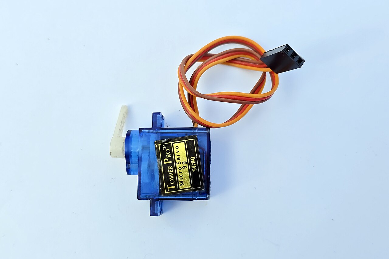
The classic micro-servo lead: three conductors into a 0.1-inch-class housing — verify pin order against your receiver, not the wire colors. Photo: Suyash Dwivedi, CC BY-SA 4.0, via Wikimedia Commons.
1. The system: three pins, 0.1-inch pitch, one partial safeguard
A servo lead is a 3-position, 0.1-inch (2.54 mm) pitch, single-row crimp housing: three sockets that slide over standard square posts — receiver pin banks, flight-controller rails, bare headers. Friction fit, no latch. The order is signal / positive / negative, with positive always on the center pin, and the color convention follows one rule: red is the center positive, the darkest wire is negative, and the lightest wire is signal.1
| Ecosystem | − (outer) | + (center) | Signal (outer) | Housing style |
|---|---|---|---|---|
| Futaba | black | red | white | J (keyed tab) |
| JR-style / Spektrum | brown | red | orange (yellow on some JR-era leads) | universal (bevel, no tab) |
| Hitec | black | red | yellow | universal |
Center-positive limits one common failure mode, but it is not reverse-insertion protection. Flip the plug 180° and the center positive pin stays put, while signal and ground trade places. Some servo/controller combinations may simply refuse to run, but others can be damaged because the servo's power return is now connected to the controller's signal output; vendor guidance explicitly warns that plugging a servo in backwards can break the servo or the device driving it.2 Treat reversal as an electrical fault, not a supported state: verify pin order at both ends before power, not "match the colors."
The signal pin itself carries a logic-level pulse train from the receiver or controller — it is a signal, with everything the power vs signal page says that implies: the power pins do the heavy lifting, and the signal pin must never be asked to.
2. JR vs Futaba — two housings, one pinout
The marketplace's "JR-style vs Futaba-style" distinction is real, small, and purely mechanical:3
- Universal / JR style — the housing has a bevel (chamfered corners) that denotes orientation; JR's "safe connect" chamfer geometry resists wrong-way insertion into proper sockets. No tab.
- Futaba J — the same housing idea plus a keyed index tab on the signal-side edge, matching the slot in Futaba receivers.
In modern production the two are electrically identical with the same pin order. Universal/JR plugs fit Futaba gear; a Futaba J's tab can refuse some third-party sockets and shrouds — and the time-honored field fix, shaving the tab off, literally converts a J into a universal housing.3 European brands historically sorted into the same two camps (Graupner leads sold as JR-type, Robbe as Futaba-type), which is why old-continent listings name pairs like "JR/Graupner" and "Futaba/Robbe."
Marketplace decoder: "servo plug," "S connector," "JR-style," "Futaba-style," "universal," and "3-pin Dupont" all point at this same interface — with all the listing-title skepticism that implies.

The system in one card: + holds the center under reversal, but signal and ground still swap; the J housing is a universal plus a tab — and a bare header row will happily accept a shifted or reversed plug.
3. The ghost in the drawer: old Airtronics
One historical fleet breaks the rules above. Older Airtronics servo leads (before the brand's "Z" connector) used a different polarity arrangement — connecting one to JR/Futaba/Hitec-convention gear without rewiring or an adapter can burn out the servo, the receiver, or both, and dedicated conversion adapters exist precisely because of this.4 If a vintage Airtronics/Sanwa-era servo surfaces in an inherited parts bin, identify the connector generation before it ever sees power.
The transferable lesson outlives the brand: colors and even polarity are the maker's choice. No-name marketplace servos get the same treatment — pin order verified against documentation, not assumed from hue.
4. "It's just Dupont" — true, and a trap
The servo connector is the most famous citizen of the 0.1-inch header ecosystem, and both halves of that sentence matter.
Why it's true: 2.54 mm pitch and standard square posts mean servo leads mate with the entire header world — that's why servo testers, breadboard jumpers, dev boards, and flight controllers all interoperate without anyone signing a standard.
Why it's a trap:
- Bare header rows have no keying. A receiver puts molded walls around its pin bank; a bare three-pin row on a dev board offers no such help. A servo plug on a bare row can land reversed and shifted one pin over — both fit perfectly. Count pins, then look again.
- Housing ≠ housing. Generic Dupont shells lack the bevel/safe-connect geometry, and kit-grade terminals differ from genuine servo-lead terminals in plating and retention — the connector-kit lesson applies verbatim.
- Friction is the only retention. Same as every Dupont connection: vibration walks plugs off. Section 7 is about fighting that.
5. Three pins carrying a motor: the current problem
Here is the tension at the heart of the interface: it's a signal-class connector that powers a motor.
- The connector class: servo maker ProModeler's engineering note puts the 0.1-inch pin class at roughly 3.5 A continuous / 5 A intermittent per the pin manufacturers' own ratings5 — consistent with the 3 A that Amphenol publishes for its genuine MiniPV 2.54 mm crimp family (the "Dupont" ancestor, cited on the headers page). No governing spec backs any of this, and clone terminals owe you nothing at all.
- The stall reality: manufacturers publish stall currents now, and they've caught up with the connector. Savox lists a standard-size high-torque digital at 3.5 A stall @ 7.4 V and a 1/5-scale servo at 5.7 A stall @ 7.4 V6 — at and past the connector class, delivered through one + contact and one − contact.
- The wire ladder: per vendor documentation, 26 AWG is the standard-to-light-duty servo wire, 22 AWG the heavy-duty choice, and 20 AWG the heaviest that practically fits the housings.7 The wire, the crimp, and the contact are one series circuit — an undersized any-of-them sags the servo's supply exactly when it's fighting hardest.
What the failure looks like is rarely smoke: it's voltage sag at the servo — lost torque, jitter, rebooting receivers — and plugs that come back warm. The giant-scale world's answers are instructive: short heavy leads, servo power distribution boxes instead of daisy chains, and higher-voltage "HV" servos that move the same watts at fewer amps. When a build's numbers genuinely exceed the class, the answer is not a braver 3-pin plug — it's a power-rated connector and the power vs signal split.
6. The receiver rail and the BEC
The per-servo math has a system-level sequel: every servo's current arrives through the receiver's (or flight controller's) servo rail, and that rail is fed by a BEC — a battery eliminator circuit, usually inside the ESC — or by a separate battery or regulator.
- Linear vs switching matters. A linear BEC burns the voltage difference as heat, so its deliverable current falls as pack voltage rises; switching BECs regulate efficiently instead.8 "The ESC has a BEC" is not a number — find the rated current at your pack voltage.
- Sum realistic peaks. Multiple digital servos hitting load together is the design case, not the corner case. An undersized BEC sags the rail, the receiver browns out and resets, and in the air that's the crash report.
- The rail's feed is a connector too. On many setups the BEC's output reaches the rail through the same 3-pin connector class — one more place the §5 arithmetic applies, and the reason big systems run dedicated power feeds or distribution boxes rather than pushing a whole model's servo current through one plug.
7. Extensions, Y-harnesses, and staying connected
- Every extension adds two more contact interfaces in series — more resistance in the servo's supply and two more friction joints that can walk apart. Fewer, shorter, heavier runs beat daisy chains.
- Gauge over length: on long runs, match or exceed the servo lead's own gauge — the vendor wire ladder in §5 is the menu.7
- Y-harnesses drive two servos from one channel — remember the upstream contacts now carry both servos' current.
- Retention is a purchasable part: purpose-made safety clips/locks click over a mated pair and turn a friction fit into a captive one;1 heat-shrink over the joint is the field expedient. Either beats discovering the elevator extension unplugged itself.
- Dress the run. Anchor extensions so vibration and control-surface movement work the airframe, not the plug — and tug-test every crimp before it flies.
8. The rules that never change
- Verify pin order at both ends before power. Colors are hints; order is the standard.
- Genuine or reputable terminals only — the contact spring and plating are exactly what kit-grade parts get wrong, and this connector's job is holding a motor's supply together.
- Stall current sizes the system — wire gauge, extension count, BEC rating, and whether the 3-pin class is adequate at all come from the servo's stall figure, not its torque headline.
- Retention is your job. Friction fit plus vibration equals eventual disconnection unless a clip, shrink, or dressing says otherwise.
- Outgrow it consciously. When the project stops being hobby-class, When Hobby Connectors Are Not Enough takes over — and an industrial servo axis speaks M23, not three pins.
Source status
No governing specification exists for this family — that fact organizes the whole page. Pin-order and color conventions are cited to a servo manufacturer's documentation and a hobby-industry reference;1 the reverse-insertion damage warning to Pololu's servo guidance;2 housing geometry (bevel, J tab, shave-to-universal) to vendor documentation of the de-facto standard;3 the old-Airtronics polarity difference to conversion-adapter documentation;4 the contact-class current to a servo manufacturer's engineering note quoting pin-manufacturer ratings;5 stall currents to Savox's published specifications;6 and the wire-gauge ladder to vendor documentation.7 None of it transfers to clone leads or kit terminals, and the exact servo's manual plus the exact terminal's spec always decide. Tracked in Hobby Source Notes.