Screw Terminals, Spring Clamps, and Ferrules
Terminal blocks are the connector nobody thinks of as a connector — which is exactly why they fail like one. Every power distribution board, motor driver, thermostat, and "no soldering required" kit clamps a wire somewhere, and the clamp is a real electromechanical interface with a gauge range, a torque spec, a wire-preparation rule, and failure modes that show up months later as heat. This page is the discipline the screw never tells you about.
1. The clamp-style map
"Screw terminal" is a family of clamping mechanisms, and the mechanism decides the rules:
| Style | How it clamps | Where you meet it | The thing to know |
|---|---|---|---|
| Rising clamp / wire protector | Screw lifts a pressure plate; the screw never touches the wire | Quality PCB blocks, DIN-rail blocks | The style to prefer — the plate spreads force and won't chew strands |
| Direct/plate screw | Screw tip bears on the conductor | Cheap PCB blocks, barrier strips | Screw rotation can birdcage stranded wire; ferrules earn their keep here |
| Barrier strip | Screw + captive wire or ring/spade lug | Older equipment, audio, mains-adjacent wiring | Really a lug interface — crimp rings/spades beat bare wire under a screw head |
| Push-in / cage-clamp spring | Spring presses the conductor against a busbar | Modern DIN-rail and PCB blocks | Vibration-tolerant, torque-free — but stranded wire wants a ferrule to push in |
| Lever (Wago-style) | Operator-actuated spring | Field splices, lighting, power distribution | The one clamp class with deep genuine-part documentation — the full story, both size classes and both rating systems, in §3 below |
| Pluggable two-part | Any of the above, in a header-and-plug pair | Motor drivers, industrial PCBs | The unplug-to-service upgrade — and home of the pitch trap below |

Three ways to squeeze a wire, and the ferrule that gives stranded wire a solid, clampable end. The mechanism decides whether the screw touches your conductor.
2. The numbers nobody reads
- Pitch, again. PCB terminal blocks and pluggable headers come in pitch families — 5.08 mm (0.2"), 5.0 mm, 3.81 mm, 3.5 mm, 2.54 mm — and pitch tracks the voltage class: wider spacing, more creepage, higher rating. The measure-don't-eyeball rule applies with teeth here, because 5.0 mm and 5.08 mm pluggable halves will visually "fit" and bind or mis-seat across enough positions — the classic lookalike trap at power level.
- The gauge range is a range — a minimum and a maximum, and often different for solid, stranded, and fine-stranded wire classes. A 24 AWG signal wire in a clamp sized for 12 AWG is retention theater.
- Strip length is printed on the block (or its datasheet) for a reason: too short clamps insulation, too long leaves bare wire exposed above the clamp.
- Torque is a specification, not a feeling. Real terminal blocks publish a tightening torque; under-torqued joints heat, over-torqued ones damage strands or the block. Whether a connection needs scheduled inspection or re-tightening is also product-specific: some conventional screw connections require it, while self-locking designs are explicitly sold as maintenance-free.1 Get both the installation torque and the maintenance instruction from the exact manufacturer's documentation — never impose a generic re-torque schedule.
- One conductor per clamp point unless the datasheet explicitly rates two — and two-wire ratings usually require same gauge, same type.
- Vibration often favors springs, but mechanism beats category. Spring and cage-clamp styles maintain force as conductors move, while ordinary screw connections may relax. Some self-locking screw-terminal designs are also qualified for vibration and maintenance-free service.1 Select from the exact terminal's vibration data and maintenance instructions, not "spring good, screw bad" folklore.
3. Lever connectors for real power work
The lever class is the one corner of this page with deep, genuine-part documentation — which is exactly why it's the field-splice workhorse. The details that matter when a lever connector carries real current, per WAGO's own documentation:23
| 221-4xx (4 mm² class) | 221-6xx (6 mm² class) | |
|---|---|---|
| Conductors | 0.2–4 mm² solid/stranded, 0.14–4 mm² fine-stranded (24–12 AWG) | 0.5–6 mm², all conductor types (20–10 AWG) |
| IEC rating | up to 32 A / 450 V | 41 A / 450 V |
| UL rating — same part | 20 A / 600 V | 30 A / 600 V (UL 486C) |
| Temperature class | 85 °C surrounding air | 85 °C surrounding air |
Four things to internalize:
- The 6 mm² line exists. Most people only know the 4 mm² connectors; the 221-6xx family is the same mechanism scaled to 10 AWG and a 41 A IEC class — the difference between a lighting splice and actual power distribution.
- The IEC and UL numbers differ on the identical part. 32 A / 450 V and 20 A / 600 V describe the same connector under two certification regimes (EN 60664-based IEC characterization vs. the UL 486C listing). Design to the rating system your jurisdiction and inspection actually use — and check which system a listing is quoting before comparing parts.
- Fine-stranded without ferrules is the lever's superpower. The lever clamp is specified for fine-stranded conductors directly — the practical selection line between levers and push-in spring connectors, which want solid wire or a ferruled end.
- Carriers make it an installation. WAGO's mounting-carrier and strain-relief accessories fix 221s in an enclosure — the difference between a loose splice and a serviceable distribution point. A lever connector is still not a junction box: the moment it's mains, enclosure and local code govern.
And once more for the back: these figures are for genuine WAGO 221s — marketplace "Wago-style" levers inherit none of them.
4. Ferrules — the missing part of every stranded-wire clamp
A ferrule (bootlace ferrule, per the DIN 46228 style system) is a crimped tin-plated sleeve that turns a bundle of strands into one solid, square-shouldered pin. That's what a clamp is designed to grip. Ferrules stop strand splay and whiskering, survive re-termination, and give spring/push-in blocks something to actually push against. Two disciplines:
- Crimp them properly — a ferrule crimper with the right die, the same crimp seriousness as everything else.
- Don't trust the color. Ferrule color-coding exists in competing systems (the French and German codes assign different colors to the same sizes) — read the printed size, not the sleeve color.
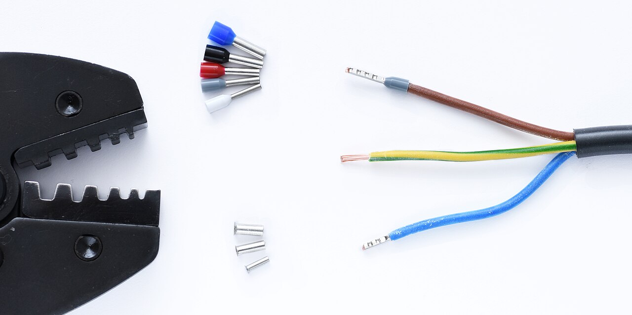
The ferrule kit and its crimper — the stranded wire's ticket into any clamp. Photo: Simon A. Eugster, CC BY-SA 3.0, via Wikimedia Commons.
5. The rule: never tin stranded wire before clamping
Soldering the end of a stranded wire and putting it under a screw feels tidy, but Phoenix Contact documents why it can loosen: the compressed solder/tin mass can fracture and change shape, and copper and solder expand differently during thermal cycling until the conductor is no longer clamped correctly.4 The failure arrives later as a loose, high-resistance power joint. Use the conductor preparation the exact terminal permits — commonly bare stranded wire in a suitable rising clamp or a properly crimped ferrule — and tighten to the published specification.
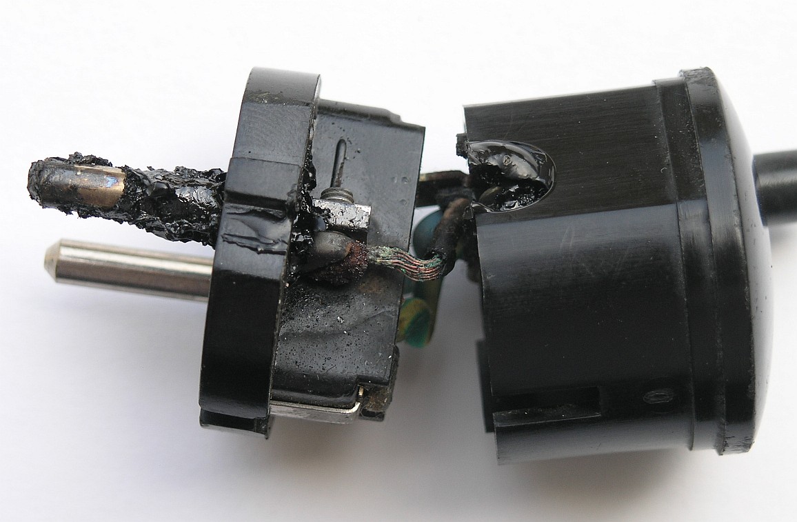
A documented result of clamping tinned stranded wire: the connection loosened and heated inside this mains plug. This is a failure example, not a general-purpose assembly reference. Photo: HansPL, released into the public domain, via Wikimedia Commons.
6. Traps
- Tinned wire under a clamp — see above; the tidy-looking one is the fire risk.
- Two conductors into one clamp point. Same disease as doubling wires into one crimp: clamps are specified for one prepared conductor unless the block's documentation says otherwise. Where two stranded wires genuinely must land together and the terminal's size range allows it, twin ferrules (one sleeve made for two wires) turn them into a single qualified end — the purpose-made answer, versus hoping the screw catches both.
- Stray strands. One whisker outside the clamp is a short waiting for a neighbor. Twist, ferrule, inspect.
- Terminal blocks are not strain relief. The clamp holds the conductor electrically; the cable needs its own anchor before the block, always.
- The 5.0 vs 5.08 pluggable mismatch — measure across all positions ÷ (N−1), per the pitch page.
- "12 A" clone blocks. Marketplace terminal strips carry ratings with nothing behind them — the same kit skepticism applies to green blocks as to connectors.
- Re-stripping into the same clamp forever. Clamps have finite re-termination cycles too; when the block's had a hard life, replace it.
- Mains voltage. The moment a terminal block carries mains, you've left this guide's lane: enclosure, creepage, touch protection, and local electrical code govern — not hobby judgment.
7. When to move to the engineering track
Field-serviceable distribution done right — DIN-rail terminal blocks in an enclosure with documented torque and wire prep — is the professional version of this page: see §12.3, terminal blocks in the family map, and, when the wiring leaves the bench, When Hobby Connectors Are Not Enough.
Source status
Lever-class figures — both size classes, both rating systems — are cited to WAGO's own family and product pages.23 The maintenance-free screw-design counterexample and the tinned-wire loosening mechanism are cited to Phoenix Contact.14 Clamp-style anatomy, strip-length/gauge-range/one-wire rules, and the pitch families are identification- and process-level, deferring numbers to the exact block's datasheet throughout. Representative torque-class figures remain an open source target in Hobby Source Notes. DIN 46228 is named as the ferrule style system without reproducing its tables.