Anderson Powerpole: The Genderless Power System
The Powerpole is what a power connector looks like when it's designed as a system instead of a plug: genderless single-pole housings you stack into whatever arrangement you need, tin- or silver-plated wiping contacts selected for the duty, and one housing that accepts three different current classes of contact. It's the standard on ham radio benches, combat robots, and DC power distribution for good reasons — and it comes with three disciplines (orientation, current-class, and contact finish) that this page makes explicit. It is also, per the section below, a power connector that keeps getting drafted into signal jobs it shouldn't do.
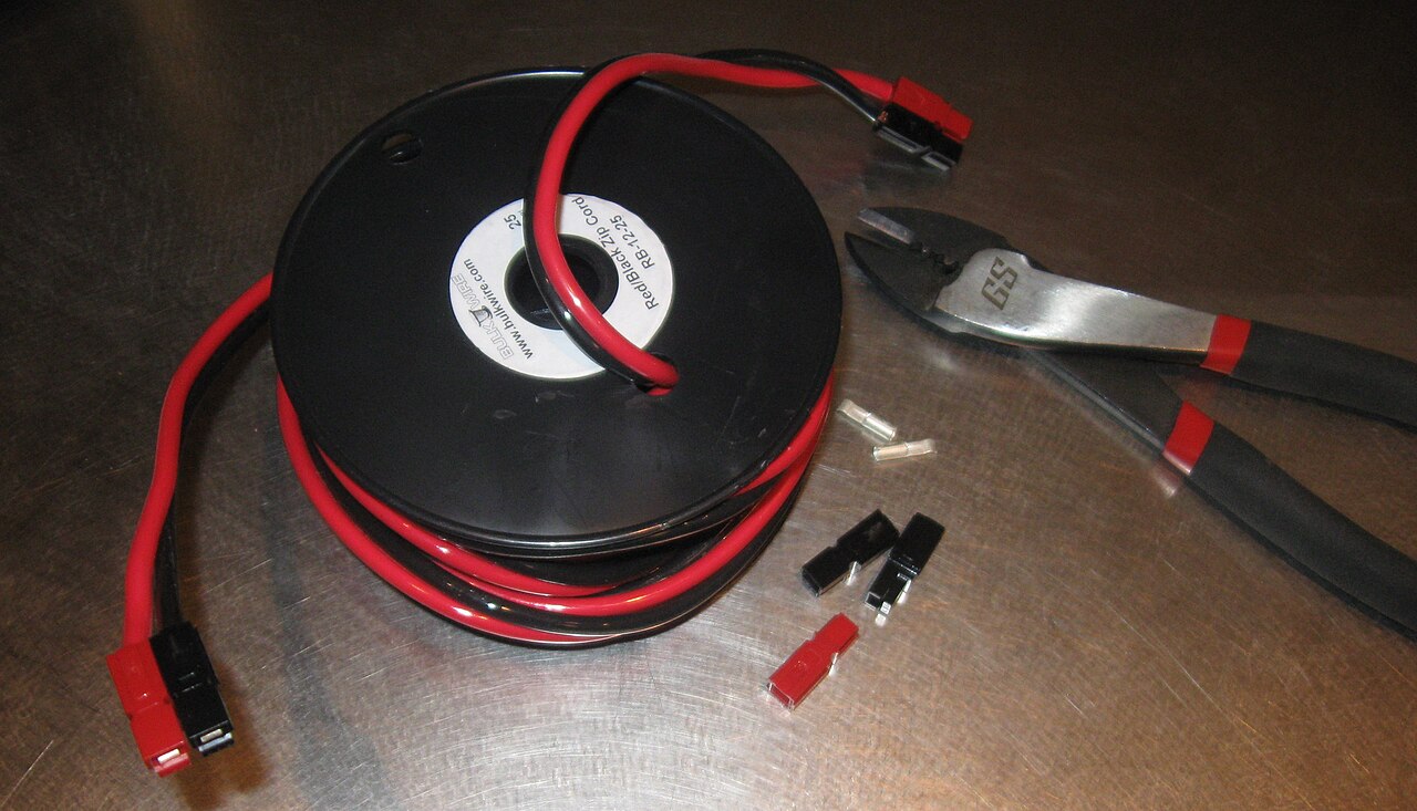
Housings, loose contacts, wire, and the crimper — the genderless quick-disconnect workflow in one frame. Photo: 4dtext, CC BY-SA 3.0, via Wikimedia Commons.
1. The system: one housing, three contacts
The famous PP15/45 family is a single housing family that accepts 15 A, 30 A, and 45 A contacts interchangeably — the contact you pick is set by your wire gauge (#20 through #10 AWG), and every combination mates with every other. Anderson's product specifications rate the series up to 55 A per pole, with wire and PCB contacts sharing the same housings.1 The flat-wiping contacts are offered with tin or silver plating, and the finish changes the published mating-cycle class: tin is the lower-cost lane; silver is the high-cycle lane.2
Three system-level facts to internalize:
- Housing color is identification only. Every color of same-size Powerpole mates with every other color. Red-to-black mates as happily as red-to-red — the colors are your convention, not a mechanical key.
- Housings dovetail. Single poles slide together side-by-side and top-to-bottom into blocks; a roll pin (or retention clip) through the dovetail locks a pair into a permanent assembly. This is how "a Powerpole" becomes a 2-pole, 4-pole, or any-pole connector.
- Contacts are removable. The detent-spring retention that clicks a contact home also lets you extract and re-terminate — Powerpole assemblies are serviceable, not disposable.
2. PP15/45 in detail — the numbers everyone using it should know
The rest of the ladder is context; this is the connector on your bench. All figures come from Anderson's own PP15/45 product specifications:1
| Spec | Value | What it means in practice |
|---|---|---|
| Mating cycles, wire-to-wire, no load — tin contacts | 1,500 | Suitable for substantial service, but not the same durability class as silver |
| Mating cycles, wire-to-wire, no load — silver contacts | 10,000 | The high-cycle choice for daily connect/disconnect service; plating is part of the part-number decision |
| Voltage class | 600 V (UL) | An insulation class, not an invitation — DC arcing behavior on disconnect is governed by the load, not the label |
| Current | up to 55 A per pole | With the 45 A contact and matching wire, per the published conditions |
| 15 A contact | #20–#16 AWG barrel | The light-wire end of the system |
| 30 A / 45 A contacts | through #10 AWG | Pick from the published wire-gauge table |
| Low-detent contacts | ~3 lbf mating force | A catalog variant most people don't know exists — for interfaces mated constantly, or by hands that can't fight the standard detent |
| Finger-proof housings | touch-safe variant | For panels and anything a stray finger (or screwdriver) can reach |
The principles that organize the whole table: the contact matches the wire, and the plating matches the duty. You pick the contact whose barrel fits your wire gauge; the housing accepts any of the three; and the safe current follows the contact-plus-wire pair in the product specifications — a 45 A contact on #16 wire is not a 45 A circuit. Then choose tin or silver from the required cycle life and switching duty. Undersized wire in an oversized barrel is also a bad crimp waiting to happen, which is the same crimp-integrity story as everywhere else.
The cycle figures above are the datasheet's no-load wire-to-wire values. The same document separately reports 5,000 cycles under IEC 60512 Test 9a for its stated PP45 configuration; do not combine a plating-table value, an IEC qualification result, and hot-plug capability into one universal family rating.2
Two variant notes worth knowing at order time: the low-detent contacts trade retention force for mating ease — a deliberate spec choice, not a defect — and the finger-proof housings are the answer when a Powerpole faces the outside of a panel. Both are ordinary catalog items; both are invisible if you only ever buy the standard kit.
3. The family ladder
| Family | Wire range | Current class | Notes |
|---|---|---|---|
| PP15/45 | #20–#10 AWG | 15/30/45 A contacts; up to 55 A per pole1 | The standard: bench, ham, robotics |
| PP75 | #16–#6 AWG | up to ~120 A per pole class3 | Same philosophy, bigger copper; dovetails with its own size only |
| PP120 / PP180 | up to 3/0 AWG (PP180) | hundreds of amps per pole; PP180 to a ~350 A / 600 V class per Anderson's product specifications3 | The heavy end of the same genderless idea |
| Anderson SB family | battery-class | per series | A different system: single-housing multi-pole connectors keyed by color — the forklift/battery world. See the high-current DC path |
Sizes do not intermate across the ladder — a PP45 and a PP75 are different connectors — and note the SB distinction: in the SB family, color is the key (different colors deliberately don't mate), the exact opposite of Powerpole color behavior. Know which system you're holding.
4. Genderless discipline: the orientation IS the polarity
A genderless connector has no built-in polarity protection — your assembly convention is the only thing preventing a reverse connection. The amateur-radio emergency services solved this by standardizing one arrangement, and it's worth adopting even if you never key a radio:
The ARES/RACES standard: red on the right, tongue on top, viewed from the contact side — "Red Right, Tongue Top."4 Of the four ways you can dovetail a red/black pair, two won't mate with a standard-built pair at all — and one mates perfectly with reversed polarity. That last arrangement is the whole argument for building every pair in your fleet to one convention, pinning it, and never freelancing.

The system in one card: contact clicks into housing, housings dovetail into pairs (pin the dovetail), and the pair gets built to one orientation — because the wrong arrangement can still mate, reversed.
5. Assembly details nobody documents
- Crimp, then click. Crimp the contact to the wire (a proper Powerpole crimper, with the same inspection seriousness as always), then insert until the detent spring clicks over the contact. Solder is possible on these contacts but crimping is the repeatable, inspectable path.
- The seating failure. A contact pushed in at the wrong depth — or with the contact tip riding over the spring instead of under it — will look assembled and then push back or mis-mate under insertion force. Tug-test every pole after the click.
- Pin the pairs. An unpinned red/black pair can shear apart in a drawer and get reassembled wrong — the roll pin turns a convention into a mechanical fact.
- Dress the wire. Poles accept the wire straight in with no built-in strain relief; anchor cables near the connector, especially on anything that moves.
- Fuse near the source. The Powerpole habit of building distribution networks means the battery side deserves a fuse before the first splice — power vs signal rules apply to the whole tree.
6. Ridiculously useful for power — the wrong answer for signal
Powerpoles are so convenient that they get drafted into signal jobs, and it's worth saying plainly why that's a misuse:
- Scale. One Powerpole per circuit is enormous next to any signal family — a 6-signal interface in Powerpoles is a brick of housings doing a job a single latched connector does better.
- Wrong contact lane. The system is engineered and characterized for power — flat-wiping contacts sized in tens of amps, offered in tin and silver. Low-level signals are outside its documented lane; nothing in the product documentation speaks to dry-circuit reliability, and you'd be designing on vibes. (The engineering track's Low-Level Signals and Contact Design is the general version of this rule — and the test to apply to any family.)
- No latch, no shield, no key. Friction/detent retention with no positive latch, no shielding story for data, and polarity/keying that exists only by convention — three strikes for signal work. Keyed, latched signal families (internal PCB harnessing, or the hobby families map) are the right tools.
- The legitimate gray zone is low-current power — a 500 mA accessory feed in a Powerpole fleet is fine, because it keeps the fleet on one system. Signal ≠ small power; route data and sense lines through a signal connector.
And the environmental rule carries over from the professional side: Powerpoles are unsealed — outdoors they need a boot, an enclosure, or a sealed family instead.
7. Mounting and distribution
The system extends past the cable: panel-mount frames put Powerpole pairs through an enclosure wall, retention clips hold pairs in racks, and the ham ecosystem is full of fused distribution strips built around the standard pair (RIGrunner-style, from several vendors). That ecosystem is the argument for adopting the ARES orientation — every commercial accessory assumes it.4
8. The rules that never change
- Not load-break. Like every family in both guides: don't unplug under load unless the exact datasheet says so — battery DC arcs. De-energize first.
- Genuine parts. Powerpole clones exist and the contact spring is precisely the part a clone gets wrong. Same rule as everywhere: known distributor, genuine Anderson, matched contacts.
- When you outgrow it: SB-class for battery packs, sealed automotive for the field — the high-current path and When Hobby Connectors Are Not Enough take it from here.
Source status
PP15/45 housing, wire-range, current, voltage-class, plating, and configuration-specific cycle figures are cited to Anderson's current PP15/45 datasheet;12 the family-ladder figures for PP75/PP180 to Anderson product specifications with a distributor listing labeled as such;3 and the ARES/RACES orientation convention to emergency-service training references (a convention claim, not a rating).4 Assembly guidance is process-level. Tracked in Hobby Source Notes.