Worked Example: M12 Sensor Interface
“The sensors need to plug in somewhere” is not an interface definition, so this example keeps going until it has a documented M12 architecture. It applies the Industrial sensor and Rugged Ethernet paths to one real machine layout, with the M12 deep dive supplying the technical detail.
The scenario below is an illustrative composite, informed by a sanitized real-world A-coded/X-coded selection but not a report of any single project. The reasoning is the point, and every connector fact is stated by reference to the deep dive and decision paths, which carry the sources.
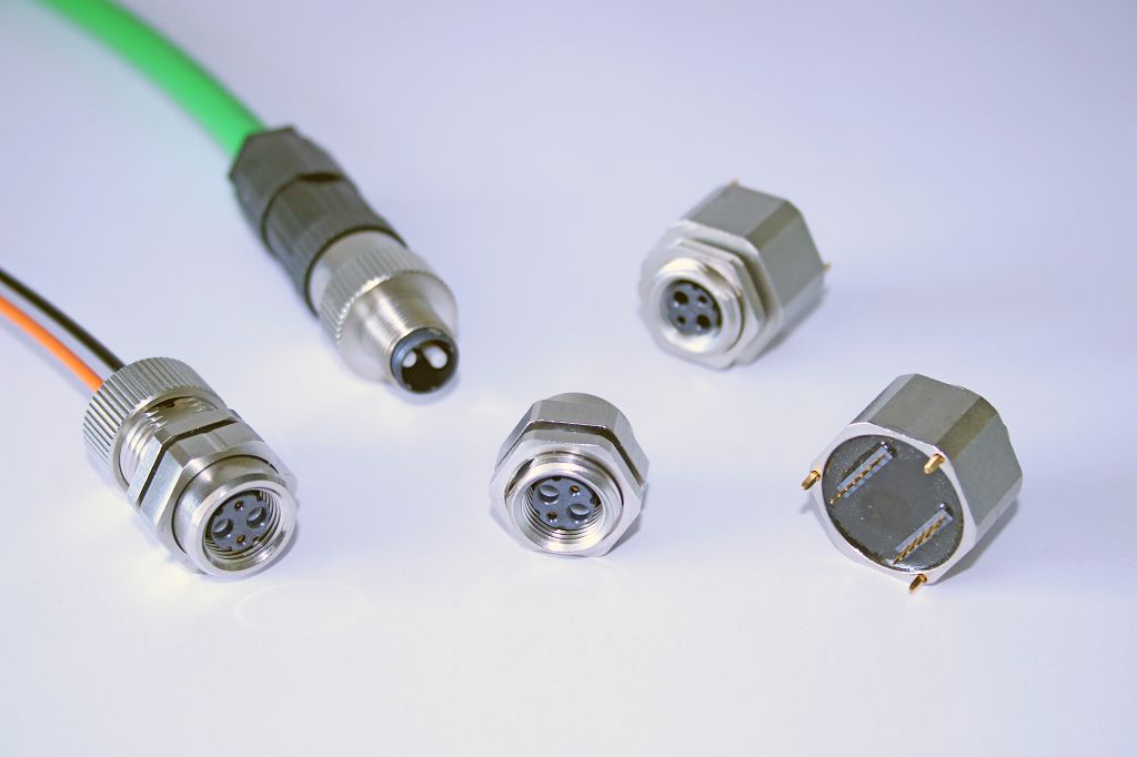
The worked example standardizes on M12, but the physical ecosystem still contains panel receptacles, molded cordsets, field-wireable bodies, and different cable exits. The exact device, coding, mounting, and service plan choose among them. Photo: Riep., CC BY-SA 4.0, via Wikimedia Commons.
Like the Selection Packet, this example teaches how to decide and document. Part numbers, counts, and lengths marked J- or TBD are placeholders. A real project replaces every one with an exact, datasheet-verified value. Don't reuse a rating from this page just because it looks close.
Scenario
A small automated assembly-and-test cell on a factory floor: a machine frame carrying part-presence sensors (inductive proximity and photoelectric), one IO-Link distance sensor on the test station, and a machine-vision camera on the inspection station whose Ethernet run goes back to the cell controller. The cell sits near a washdown area — the frame sees splash and hose mist, not submersion — and it lives on casters: it gets rolled out for maintenance, which means cables get unplugged and replugged by whoever is on shift, not by the people who built the cell.
That last sentence is most of the connector requirement. The sensors themselves are ordinary; what needs engineering is a sealed, keyed, serviceable, documented way for a rotating cast of technicians to disconnect and reconnect the cell without creating wiring faults.
1. Requirements summary
| # | Requirement | Value | Source | Status |
|---|---|---|---|---|
| R1 | Environment | Splash/mist zone; target sealed-when-mated (IP class TBD from plant spec); indoor temperature range TBD | Plant washdown spec TBD | TBD |
| R2 | Sensor circuits | n × discrete DC sensors (TBD count) + 1 × IO-Link device | Cell I/O list TBD | TBD |
| R3 | Data | One Ethernet run, camera → controller; required rate TBD from camera datasheet (GigE-class assumed below) | Camera datasheet TBD | TBD |
| R4 | Power | Sensor power over the sensor cordsets; per-circuit current TBD vs. exact part ratings | Device datasheets TBD | TBD |
| R5 | Service model | Unplug-to-move by shift technicians; no tools at the interface; mis-mating must be physically prevented | Maintenance plan TBD | TBD |
2. Candidates considered
For the sensor circuits, per the Industrial sensor path's families-to-start-with:
- M12 A-coded — the common industrial default for DC sensors and I/O, and the IO-Link device rides the same connector family (§8.1). Selected.
- M8 — viable for the compact sensors, and worth considering where space is tight. Rejected here as a standardization decision, not a technical one: one shell size across the cell means one cordset inventory, one seal system, one torque procedure, and no size-guessing during a night-shift swap.
- Hardwired cable glands into a junction box — cheapest on day one, rejected on the service model (R5): every sensor swap becomes a wiring job inside a sealed box, done by whoever is on shift — the unplug-to-service model the Industrial sensor path is built around, inverted.
- Sealed automotive families (DT-style) — good connectors in their own lane (rugged on a budget), rejected because the sensor ecosystem ships M12/M8 cordsets off the shelf; fighting the ecosystem means custom pigtails everywhere.
For the Ethernet run, per the Rugged Ethernet path:
- M12 X-coded — matches a GigE-class camera requirement (§8.1's D-vs-X note). Selected, pending R3 confirmation — if the camera actually needs only 10/100, D-coded is the honest choice, not X "to be safe by default."
- M12 D-coded — right answer for 10/100BASE-TX, rejected only if R3 confirms a GbE-class rate; this is exactly the decision §8.1 exists to keep straight.
- Sealed/rugged RJ45 — workable, rejected on the path's own checklist concerns (latch protection and sealing at a frequently-unplugged interface) plus the standardization argument: the cell already speaks M12.
3. Decision matrix
Structure per the comparison matrix template; scores are illustrative of the reasoning above, not measurements.
| Criterion | M12 A-coded (sensors) | Hardwired glands | Notes |
|---|---|---|---|
| Environment / sealing | Sealed when mated and torqued — verify the exact assembly (§8.3) | Sealed but service-hostile | mated and unmated states both matter |
| Electrical fit | Verify per-circuit current vs. exact part rating | n/a | family figures are not part ratings |
| Ecosystem / sourcing | Off-the-shelf cordsets, multiple vendors | custom every time | R5 favors replaceable cordsets |
| Service model | Unplug/replug, keyed, no tools at the interface | wiring job per swap | the deciding row |
4. Selected architecture
| Ref | Interface | Family/coding | Why |
|---|---|---|---|
| J-1…J-n | Discrete sensor circuits | M12 A-coded, 4-pin, panel receptacles on the frame's junction blocks | Industrial sensor path + R2/R5 |
| J-io | IO-Link distance sensor | M12 A-coded (IO-Link rides the same 3–4-wire connector — §8.1) | R2 |
| J-cam | Camera Ethernet | M12 X-coded, 8-pin (§8.1), shielded run | R3 + Rugged Ethernet path |
Count, placement, and panel-vs-inline decisions are recorded per run in the cable drawings (below).
5. Pinout and wiring discipline
Standing rules from the deep dive govern every assignment:
- Pin assignments come from the device datasheet and go into the ICD — wire-color conventions (e.g. the common A-coded brown/white/blue/black scheme) are example-only, never design authority (Source Notes).
- The X-coded run's cable category, shielding, and pairing follow the camera and cordset datasheets, verified per §8.1 — not "it's X-coded so it's fine."
- Every value verifies against the exact part per §8; record standard edition and datasheet revision in the ICD.
6. Molded vs. field-wireable
Decision made with §8.2's table: molded cordsets for every production run — best sealing and repeatability, and the unplug-to-move service model consumes cordsets, not terminations. Stock the lengths the cell actually needs, plus spares. A small field-wireable kit lives in the maintenance crib for emergency repair only, with the explicit rule that any field-terminated cable is a temporary article: log it, and replace it with the molded part at the next planned stop.
7. Documentation bundle
What "done" looks like for this interface, tying the templates together:
- Requirements table (above) with sources filled in
- Comparison matrix with the real scoring
- Pinout + cable drawing per run
- ICD entries — coding, torque, keying, mating-part references
- M12 coding cheat sheet checklist: standard edition + datasheet revision recorded
- Harness inspection checklist run on the built cables
8. What would change if…
- R3 comes back 10/100 — the camera run drops to D-coded; verify cable category and assembly rating per §8.1. Do not keep X "because faster is safer" — match the requirement.
- A circuit outgrew the A-coded current class — move that circuit to a power coding (L/T/S/K) per §8.1, not to "probably fine."
- The cell moved into the direct washdown zone — re-verify every mated and unmated rating against the plant spec (§8.3), add caps to every unmated receptacle, and re-run the sealed enclosure feedthrough path for the junction-block panels.
- Someone proposes "just use one big multipole" — that's the removable machine module path's problem statement; run it honestly before deciding.
These examples illustrate structure and process, not a released design. The datasheet, applicable standard, and program requirements decide the actual values.