Pick a connector for an RF, GPS, or radio path
RF isn't ordinary signal wiring with a fancier plug. Antenna, GPS, radio, timing, test, and video coax all need a controlled impedance and an intact shield path. This page gives a non-RF engineer enough orientation to route the problem correctly and ask useful questions. It is not a microwave design course.
If the frequency, power, or environment is high enough to be risky — precision microwave, high-power transmit, tight link budgets — an RF engineer should own the connector, cable, and launch design. This page helps you route the interface and ask the right questions, not close a microwave design.
Use this when
- The interface carries GPS, an antenna, a radio, RF test, timing, video/broadcast coax, or any other controlled-impedance signal.
- The connector and cable must preserve impedance and shielding.
- A panel feedthrough or rugged payload connection needs an RF path alongside its other signals.
Avoid this when
- The signal is ordinary low-speed discrete/analog wiring — use the normal selection workflow.
- The interface is Ethernet over twisted pair — see Rugged Ethernet.
- The design needs detailed RF launch design, microwave performance, or precision test-fixture work beyond this guide.
Families to start with
- SMA — small threaded workhorse for many antenna/GPS/board-edge RF lines. (Watch for RP-SMA, a reverse-polarity variant common on consumer Wi-Fi gear — it does not mate with standard SMA. Confirm which one you have.)
- TNC — a threaded, more vibration-tolerant cousin of the BNC.
- N-type — larger, rugged, weatherproof-capable; common on radios and base-station/antenna lines.
- BNC — quick bayonet; common for test, video, and legacy RF. Exists in both 50 Ω and 75 Ω variants that look alike but are not interchangeable.
- MCX / MMCX — snap-on miniatures for tight spaces (e.g. GPS modules).
- U.FL / IPEX-style (MHF-class) — the tiny snap-on board micro-coax on dev boards, GPS/LoRa/Wi-Fi modules, and drone gear (50 Ω, GHz-class, ultra-fine ~0.8 mm cable). These are board-assembly parts, not service ports: removal wants the extraction tool, and mating-cycle ratings are low — check the spec before planning repeated disconnects, and bring the signal to a panel via a U.FL-to-SMA bulkhead pigtail instead of cycling the board connector. Naming chaos alert: "U.FL" is Hirose's genuine series, while "IPEX"/"IPX"/"MHF" listings may or may not be the same geometry and generation — verify the mate.
- SMP / SMPM — board-to-board / blind-mate miniatures for dense, high-frequency assemblies.
- Coax contacts inside a MIL-DTL-38999 or other hybrid connector — for a rugged payload, one coax contact in an existing hybrid insert may beat a separate coax bulkhead. See 38999 §7.6.
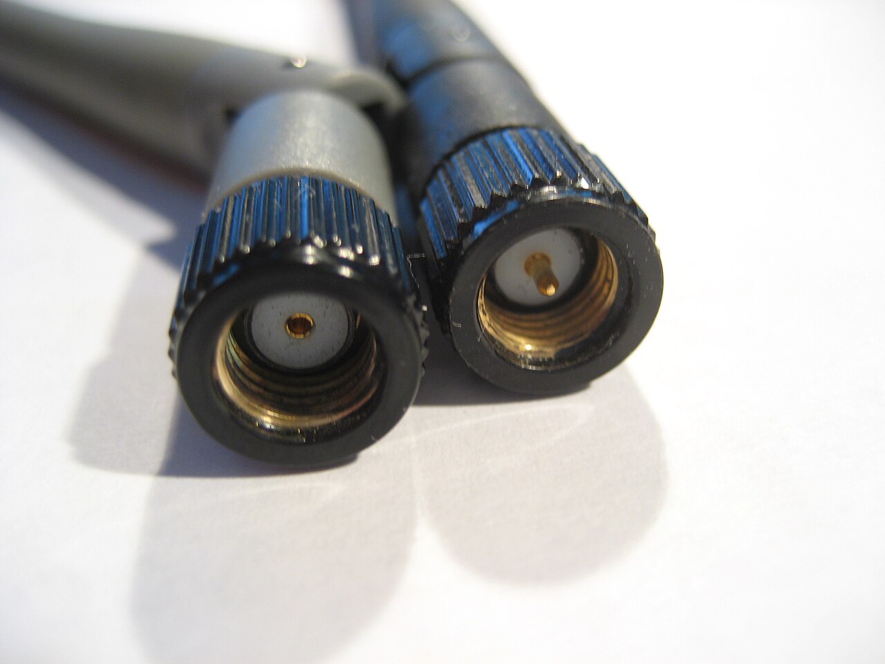
The RP-SMA trap in one frame: standard SMA and reverse-polarity RP-SMA differ only in which side carries the center pin — the shells and threads look identical, and they do not mate. Photo: Fckw kyle, public domain, via Wikimedia Commons.
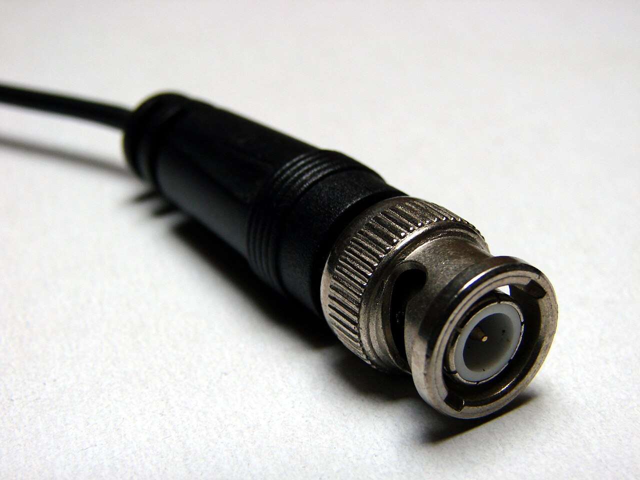
BNC male: the bayonet slots in the coupling ring are the giveaway — quick quarter-turn mating, and remember 50 Ω and 75 Ω versions look alike. Photo: Krzysztof Burghardt, CC BY-SA 3.0, via Wikimedia Commons.
Search terms
SMA connector 50 ohm RG316 crimp bulkheadTNC vs BNC RF connector vibrationN-type bulkhead antenna connector weatherproofBNC 50 ohm vs 75 ohm differenceMMCX GPS antenna connectorU.FL to SMA bulkhead antenna pigtailMIL-DTL-38999 coax contact insert arrangement
Specs to check
- Impedance — 50 Ω or 75 Ω — matched across connector, cable, and terminations. 50 Ω dominates RF/microwave/GPS/comms; 75 Ω dominates video/broadcast. Do not mix visually similar variants.
- Frequency of the exact connector and cable together — a family name is not a frequency rating.
- Power handling for transmit paths (part-specific).
- Cable compatibility — the exact coax the connector is designed to terminate (e.g. RG316, RG174, LMR-class), and the correct crimp/clamp.
- Mating torque where the connector specifies one (common on threaded RF interfaces) — use a torque wrench.
- Environment — weatherproofing, sealing, and caps for outdoor/panel use.
Minimum RF connector decision fields
Capture these before you choose — they are decision-support fields, not ratings. If you can't fill a row, that's the row that bites later.
RF connector selection is not only mechanical fit. Frequency range, impedance control, launch geometry, cable assembly quality, bend radius, torque, return loss, insertion loss, and environmental sealing can dominate performance.
| Field | Record |
|---|---|
| Signal / function | GPS / antenna / radio TX/RX / timing / video / test |
| Frequency range | per the link design |
| Characteristic impedance | 50 Ω / 75 Ω — matched across connector, cable, termination |
| Connector family | SMA / TNC / N / BNC / MCX/MMCX / U.FL-class / SMP/SMPM / coax contact in a hybrid |
| Cable type | the exact coax the connector is designed to terminate |
| Insertion loss budget | dB at frequency, from the link budget |
| Return loss / VSWR requirement | per system requirement |
| Power at frequency | transmit paths — part-specific |
| Environmental sealing | rating + test condition, if external |
| Mate-cycle expectation | service model |
| Torque requirement | value + torque wrench, per datasheet |
| Vibration / strain relief | boot/backshell/support strategy |
| Connector saver required | yes / no |
| Test equipment interface | what the port must mate with in test |
| RF owner / reviewer | who signs off |
| Source document / datasheet | identifier + revision/date |
Parts people forget
- The matching cable and the correct crimp/clamp tooling for that exact coax.
- A torque wrench for threaded RF interfaces that specify a mating torque.
- Connector savers on high-cycle test ports, so wear lands on a cheap sacrificial adapter.
- Weather caps / protective caps — contamination on an RF interface degrades performance and can damage the mating face.
- Bulkhead hardware and a panel gasket for feedthroughs.
See What People Forget.
Common traps
- Selecting by pin count / "it fits." RF selection is impedance, frequency, power, cable compatibility, shielding, environment, and service model — the connector, cable, termination, launch geometry, and panel transition are one system.
- Mixing 50 Ω and 75 Ω BNCs (or SMA/RP-SMA) because they look alike.
- Skipping the torque wrench on threaded RF connectors — over- or under-torque both degrade the match and can damage the interface.
- Long shield pigtails at the panel transition — inductive, and they radiate. Keep the shield/ground path short and circumferential; see EMI, shielding, and bonding (§5.7).
- Assuming a family frequency ceiling. As a rough ordering, SMA-class connectors are generally used at higher frequencies than N/TNC/BNC families — but the exact ceiling is part- and cable-specific, so read the datasheet.
Questions to ask a vendor/FAE
- What is the impedance and frequency rating of this exact connector on the cable I'm using?
- What crimp/clamp tool and die does this connector-cable combination require?
- Is a mating torque specified, and what is it?
- For a bulkhead: what panel thickness, cutout, and gasket achieve the sealing I need?
- Is there a coax-contact option for my existing hybrid connector instead of a separate bulkhead?
Example documentation bundle
- A comparison-matrix row capturing impedance, frequency, cable, and environment — not just the connector name.
- A source-controlled cable/RF interface definition: connector, cable type, impedance, torque, and shielding/bond, in the ICD.
- A cable drawing note for the coax, its termination, and the panel transition.
Related: RF connectors — a brief orientation (§2) · EMI, shielding, and bonding (§5.7) · Coax/twinax in a 38999 (§7.6) · Defense / rugged external I/O · Practical Checklist.