Pick a connector for a removable machine module
If a control box, machine section, test-cart module, or panelized subsystem gets pulled for service, one confident disconnect beats a fistful of loose plugs. This is where industrial rectangular / Han-style connectors earn their keep: power, signal, and sometimes data through one large, serviceable interface.
Use this when
- A module or subsystem is removed for service and you want one confident disconnect, not a fistful of loose connectors.
- The system is industrial or machine-control oriented, in a control panel, cabinet, cart, or DIN-rail ecosystem.
- Mixed power / signal / data through one housing would simplify the interface.
- Panel space is available and serviceability / technician access are primary requirements.
Avoid this when
- Weight and size are tightly constrained — small aerospace payloads, handheld devices. See the compact circular families (M12, MIL-DTL-26482) instead.
- The interface needs defense/aero qualification or a 38999 ecosystem — see Defense / rugged external I/O.
- It is a simple sensor cable where an M8/M12 is cleaner.
- It is internal PCB harnessing — see Internal PCB harnessing.
- It needs RF/coax/fiber discipline the selected insert can't support — see the RF/GPS/radio path and, for fiber, §2's orientation.
Families to start with
- Industrial rectangular / heavy-duty connectors — the general category (hood + housing + insert), covered by IEC 61984-class products.
- Han-style modular systems — a hood/housing frame that accepts modular inserts: power modules, signal modules, data (including Ethernet and pneumatic) modules mixed in one frame.
- Single-piece inserts (e.g. Han E-class) where you don't need modularity — simpler and cheaper than a modular frame.
Termination is available in crimp, screw, or cage-clamp; coupling is usually a lever or single/double lever lock. Family-level current, voltage, and mating-cycle figures for the Han E insert are in the sourced comparison matrix — verify the exact insert/hood datasheet.
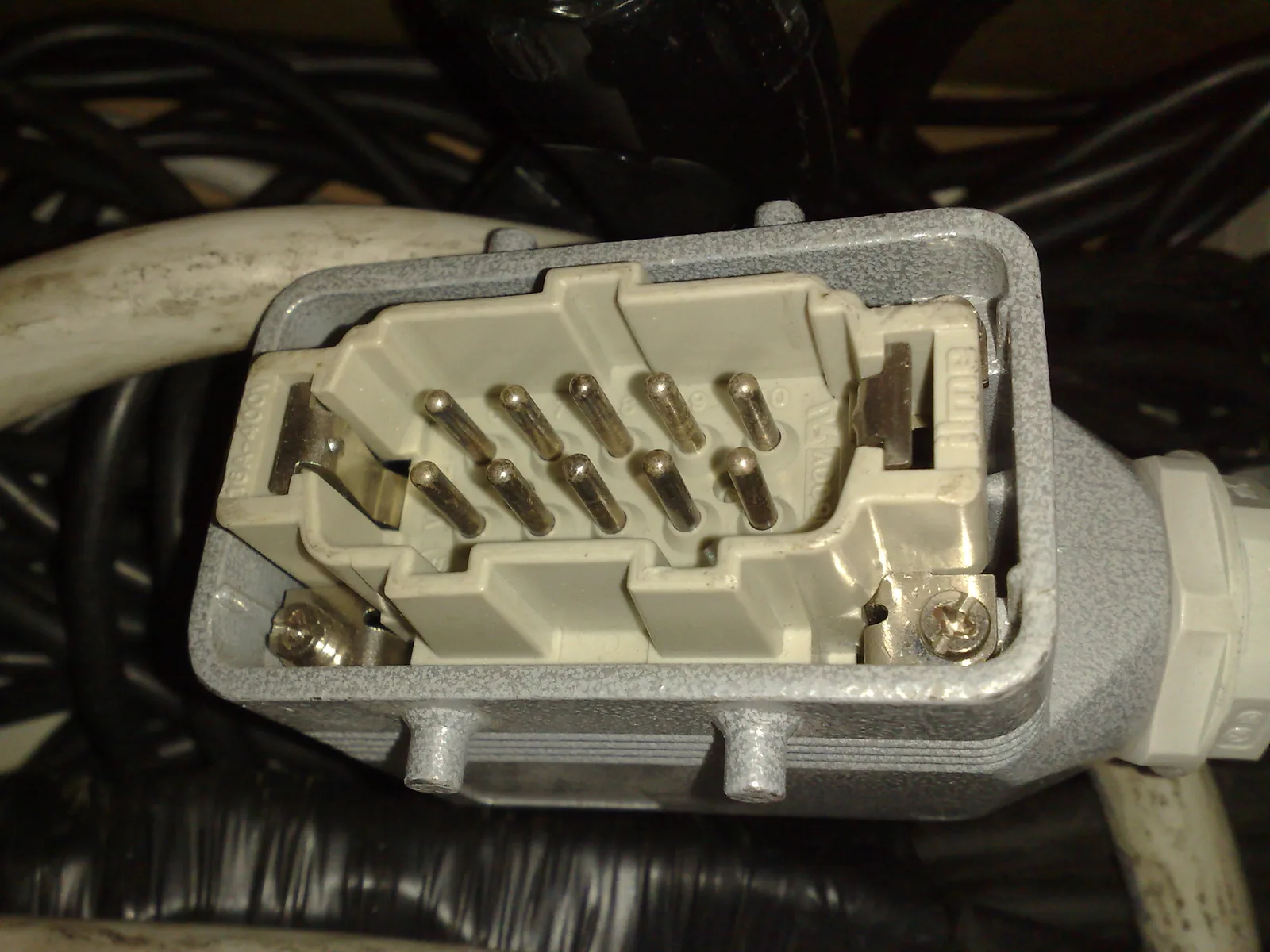
A representative heavy-duty rectangular connector with the hood open. The insert, contacts, hood/housing, latch hardware, cable entry, and mating half are separate configuration items; a complete interface has to specify all of them. Photo: Carnby, CC BY-SA 3.0, via Wikimedia Commons. Resized and converted to WebP.
Search terms
industrial rectangular connector hood housing insertHan modular connector power signal insertheavy duty connector lever lock IP65 IP67Han E crimp insert 16 Abulkhead mount rectangular connector cable gland
Specs to check
- Insert vs. hood/housing compatibility — not every insert fits every frame; confirm the size code and the insert-to-hood mapping.
- Termination type (crimp / screw / cage-clamp) and the matching tooling.
- Cable gland / entry size vs. cable OD, and the panel cutout dimensions.
- IP rating of the assembled connector — it depends on the hood, gland, gasket, and correct assembly, not the insert alone.
- PE / ground contact strategy — most frames provide a chassis-ground path; confirm it is used and bonded.
- Current per contact at temperature, and segregation if you mix power and low-level signal in one housing.
- Mating cycles for the service model; high-mating-cycle variants exist where servicing is frequent (verify the exact figure against the datasheet).
A removable module invites technicians to unplug it without checking what's energized. A connector is not load-break, hot-plug, or safe to mate/unmate under power unless the datasheet or governing standard explicitly says so. Define the de-energize/service procedure, document whether mate/unmate under power is permitted, and label the module accordingly — see the energized-connector safety warning on the high-current path.
Parts people forget
- The hood and housing (both ends), plus the gasket and cable gland.
- The locking lever kit and any coding pins if the frame supports keying.
- The PE/ground module or contact where power is present.
- Contacts + crimp/insert tooling, and blank/filler modules for unused insert bays.
See What People Forget.
Common traps
- Assuming an insert fits any hood — insert size, hood size, and mounting style must all match.
- Assuming IP rating from the family name — it comes from the correct hood, gland, gasket, and assembly.
- Mixing high-current power and low-level analog casually in one housing — segregate, and document which module carries what.
- The single-large-connector trap — one big disconnect improves serviceability but can become a single point of failure and a heavy, stiff cable. Sometimes two connectors are better than one.
- Physical-access afterthoughts — lever swing clearance, cable bend radius, technician hand room, connector orientation, and label visibility all have to work at the panel, not just in CAD.
The strength of these connectors is serviceability and modularity, not compactness. They are not just "big plugs" — the hood, housing, insert, contacts, gland, locking lever, gasket, and termination type together are the interface. Document all of them.
Questions to ask a vendor/FAE
- Which inserts are compatible with this hood/housing size, and what is the panel cutout?
- What IP rating does the assembled connector achieve with which hood + gland + gasket?
- What is the PE/ground arrangement, and is it rated for my fault current?
- What mixed-media modules (power + signal + data) are available in this frame, and how are they segregated?
- What crimp/insert tooling is required, and are high-mating-cycle contacts available?
Example documentation bundle
- A comparison-matrix row and a full interface definition: hood, housing, inserts, contacts, gland, gasket, PE path, caps.
- A source-controlled pinout / module map showing which module carries power vs. signal vs. data, documented in the ICD.
- A cable drawing with segregation, shield, and PE notes, plus an assembly/torque note.
For the end-to-end reasoning on a mixed power/signal module, see the Connector Selection Packet worked example.
Related: Standards and Families (§3) · Decision Examples · Selection Workflow · Practical Checklist.