Pick connectors for motor power + feedback cabling
A servo axis usually needs two electrical interfaces at the motor: power for the drive output, brake, and thermal wires; then feedback for the encoder or resolver signals the whole control loop depends on. Most of the family choice has already been made for you because the motor ships with receptacles and the drive ecosystem sells matched cordsets. The real job is recognizing what you have, buying the right halves, and not wrecking the EMC on the way through.
The pin counts, currents, and voltage classes below only get you oriented. The numbers that matter come from the motor connection diagram, the drive manufacturer's cable specification, and the exact connector datasheet. If this page and the drive manual disagree, the drive manual wins. In servo systems, that wiring guide is part of the control design whether people file it that way or not.
Use this when
- Connecting a servo/stepper motor to its drive — power, brake, thermal, and encoder/resolver feedback.
- Specifying the extension or replacement cable for an axis, a drag chain, or a robot joint.
- Designing a machine where motors are field-replaceable and the cable set must disconnect at the motor.
Avoid this when
- The motor is small enough that the ecosystem uses M12-class connectors for both power and feedback — see the industrial sensor path and M12 deep dive; the same discipline applies at smaller scale.
- The motor wires into a terminal box with glands and no disconnect — that's a wiring-practice problem, not a connector selection.
- A program requires mil-spec hardware — see defense/rugged external I/O.
- It's a hobby servo lead — hobby track, servo connectors.
Families to start with
- M23 circulars — the servo workhorse. A multi-manufacturer de-facto industrial standard (TE Intercontec, Phoenix Contact, binder, Hummel, and others) in two flavors you'll meet as a pair: signal/feedback inserts in the 17–19-pole class for encoders and resolvers, and power inserts with fewer, larger contacts (plus PE) for the drive output.1 Shielded versions, IP67-class sealing when mated, threaded M23×1 coupling — or quick-lock couplings (SpeedTec-style) that replace multi-turn threading with a fraction-of-a-turn action, a real assembly-time win on machines with many axes.
- M17 and M40 siblings — the same philosophy scaled down (compact servos) and up (high-power axes). Verify insert compatibility per manufacturer; the shell size number is not the whole story.
- Drive-brand cordsets — every major drive ecosystem sells pre-molded, pre-tested motor and feedback cable sets to its own spec (shield termination, twisted pairs, drag-chain-rated jacket included). This is the don't-fight-the-ecosystem lesson again: a custom-built cable has to earn its place against a catalog cordset.
- "One-cable" servo connections — several ecosystems now run digital feedback inside the power cable (single-connector motors). Treat these as proprietary drive-ecosystem interfaces: follow the drive manufacturer's cable and connector spec exactly.
- M12-class for small motors/steppers, as above.
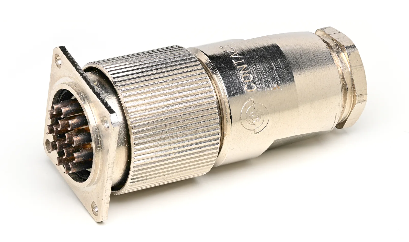
A 16-position M23-class circular connector showing the family’s threaded coupling and dense signal insert. The familiar shell does not establish the insert, keying, pinout, or motor compatibility; the motor and drive documentation still decide those. Photo: Phiarc, CC BY-SA 4.0, via Wikimedia Commons. Resized and converted to WebP.

The layout that works: two shielded cables, 360° shield termination at both ends per the drive manual, and physical separation between the switched power run and the feedback run.
Search terms
M23 servo motor power connector 6 pin PE shieldedM23 signal connector 17 pin encoder feedbackM23 speedtec quick lock servo cordsetservo motor feedback cable drag chain rated[your drive brand] motor power cable [motor series]
Specs to check
- The motor's connection diagram first. The receptacles on the motor define series, inserts, keying, and pinout — you are buying the mating halves and cable, not choosing an interface.
- Shield strategy per the drive manual — servo power cables carry fast-switched PWM edges; expect a requirement for 360° shield termination at both ends through metal backshells/glands, and follow it exactly. A pigtailed shield on a servo power cable is an EMC incident waiting for commissioning week (§5.7).
- Separation of power and feedback — separate cables, separated routing, crossings at right angles; the encoder pair's integrity is the axis's integrity.
- Contact plating on the feedback side — encoder/resolver signals are low-level; verify the feedback insert's contacts are specified for signal duty (gold-class, in most ecosystems), and never improvise feedback lines through spare power poles (low-level signal contacts).
- Current and voltage class for the power insert against the drive's continuous and peak output — plus brake and thermal-sensor conductors, which ride in the power cable in many ecosystems.
- Cable construction — drag-chain/continuous-flex rating, bend radius, jacket chemistry (oils/coolant), and the twisted/shielded pair construction the feedback protocol requires.
- Coupling type and access — threaded vs. quick-lock, and whether a hand fits the coupling nut in the installed position.
- Keying between identical-looking connectors on multi-axis machines — power vs. feedback are usually different inserts, but two adjacent axes are not.
- Mated sealing rating and unmated caps for washdown environments.
Parts people forget
- The feedback cable entirely — the power cable gets ordered, the encoder cable gets discovered at commissioning.
- Brake/thermal conductors in the power cordset spec.
- Drag-chain-rated cable where the axis moves — standard cable fails in weeks.
- The 360° backshell/gland hardware that the shield spec assumes.
- Dust caps for open receptacles during machine build.
- Spare cordsets for the maintenance stock — motors outlive cables in drag chains.
See What People Forget.
Common traps
- Building what you could buy. Hand-terminating a 19-pole shielded feedback cable to beat a catalog cordset's price is usually a false economy — the cordset's shield termination and test are the product.
- Feedback routed with power in one bundle, tray, or chain compartment. The classic intermittent-position-fault generator.
- Pigtailed shields on servo power or feedback cables — see the shield discipline in §5.7.
- Assuming any M23 mates any M23. Shell thread is not insert, keying, or shield-shell compatibility — match the manufacturer's mating chart, and treat cross-vendor intermating as a claim to verify (vendor mixing is recorded in the ICD, not improvised at purchasing).
- Mixing feedback ecosystems — encoder protocols, pinouts, and cable constructions differ per drive family even over the same connector shell.
- Ignoring the drive manual's cable length and type limits — feedback protocols and PWM output stages both carry cable constraints.
Questions to ask a vendor/FAE
- Which exact mating connector/cordset part numbers match this motor's power and feedback receptacles (series, insert, keying, shield shell)?
- Is the cordset drag-chain rated, and to what bend radius and flex-cycle class?
- How is the shield terminated at each end, and does it meet the drive manufacturer's EMC wiring requirements?
- What are the power insert's current/voltage ratings against my drive's continuous and peak output, at my ambient?
- For quick-lock variants: is the coupling vibration-rated for this axis, and is it compatible with the motor's threaded receptacle?
Example documentation bundle
- A comparison-matrix row per axis class: motor series, power cordset P/N, feedback cordset P/N, length, chain rating.
- A cable drawing or cordset spec reference with shield termination called out at both ends.
- An ICD entry per axis: connector series/inserts, pinouts by reference to the motor/drive documents, routing/separation rules.
- A harness-inspection pass covering shield continuity and coupling torque/lock verification.
Related: Industrial sensor · High-current DC power (and its energized-connector warning) · Removable machine module · EMI, shielding, and bonding (§5.7) · M12 deep dive.