Pick a connector for an industrial sensor
If somebody says “industrial sensor cable,” this is probably the lane they mean: a sealed DC sensor, actuator, or IO-Link connection on a machine. M8 and M12 dominate for good reasons, but coding, pinout, cable style, and sealing details still decide the actual part.
Use this when
- You are wiring a DC sensor, actuator, or IO-Link device.
- The connection lives in a factory or field environment and needs sealing and a positive coupling.
- You want a standard, easily-sourced ecosystem with molded cordsets available.
Avoid this when
- You need gigabit-class Ethernet — see Rugged Ethernet.
- You need real power delivery — see High-current DC power.
- The connection is internal to a PCB — see Internal PCB harnessing.
Families to start with
- M12 A-coded — 4-pin A-coded is extremely common for basic DC sensors; 3/4/5/8-pin variants cover most sensor/actuator/IO-Link needs.
- M8 — for small sensors where an M12 is physically too large (less current, fewer pins, smaller cable). See M8 — the smaller sibling.
- 7/8-inch "mini-change" — the larger US-heritage circular for sensor/actuator power distribution; you'll meet it on splitter boxes and older North American plants.
- DIN 43650 valve connectors ("Form A/B/C") — the standard rectangular interface on solenoid valves and pressure switches; frequently the other connector on the same machine as your M12s.
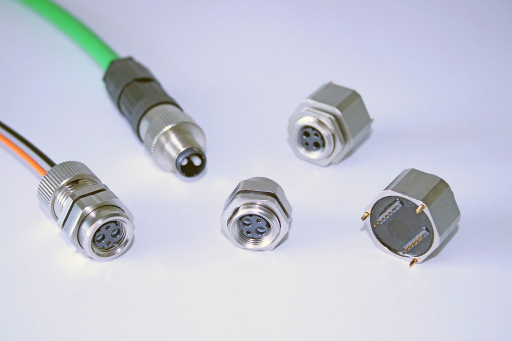
The usual sensor-cabling scale choice: M12 cordset and panel hardware beside the smaller M8 system. Photo: Riep., CC BY-SA 4.0, via Wikimedia Commons.
See the M12 deep dive for coding and pinout detail.
Search terms
M12 A-coded 4-pin panel mount sealed sensor connectorM8 sensor connector molded cordset7/8 inch mini-change power cordsetDIN 43650 form A solenoid valve connector
Specs to check
- Exact coding and pinout — not all 4-pin M12 pinouts are the same.
- Current per contact — A-coded connectors are commonly in a low-single-digit-amp class, but the exact figure is connector/cable/temperature dependent; confirm the datasheet (see M12 §8.1).
- IP rating of the complete, mated assembly — and whether the unmated panel side is sealed only when capped.
- Coupling torque — an example value only; use the manufacturer's number and a torque tool.
- Cable OD vs. the gland range, and vibration requirement.
- Signal level — a 24 V switched sensor line is forgiving; mV analog or high-resolution measurement lines are not, and want gold-class contacts and fretting-aware mechanics (low-level signal contacts).
Parts people forget
- The mating cordset / connector (both halves).
- A cap for the unmated panel connector.
- The torque spec and tool.
See What People Forget for the full list.
Common traps
- Assuming all 4-pin M12 pinouts are identical (they aren't).
- Using an A-coded port where the application actually needs D-, X-, or a power coding.
- Assuming the IP rating applies while the connector is unmated.
Questions to ask a vendor/FAE
- What is the exact mating part, and is it available as a molded cordset in the lengths I need?
- What is the cable OD range for the field-wireable version?
- Is the IP rating stated mated, unmated, capped, or panel-mounted?
- What coupling torque is specified?
- What alternate coding/keying options exist so adjacent cables can't be swapped?
Example documentation bundle
- A connector selection table row with the requirement, candidates, and choice.
- A source-controlled pinout.
- A cable drawing and an ICD entry.
Related: Decision Examples · Selection Workflow.