8. M12 Deep Dive
M12 is everywhere in industrial automation: sensors, actuators, IO-Link, CAN, industrial Ethernet, and distributed I/O. The shell size is the easy part. Coding, pinout, cable construction, torque, and the exact assembled sealing claim are where the real decisions live.
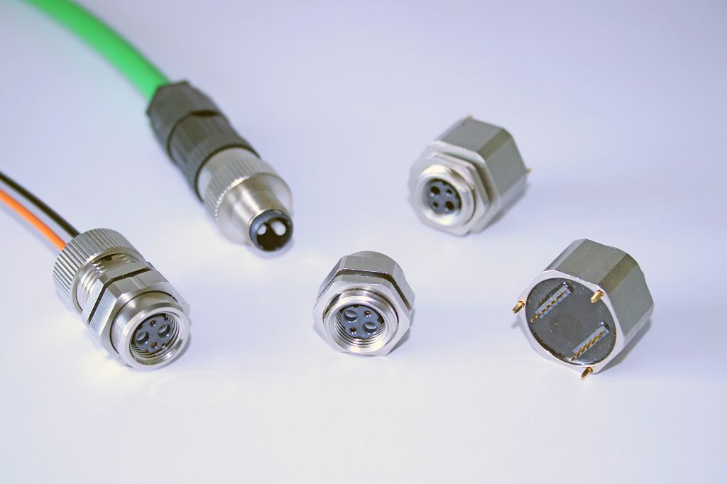
The M12 ecosystem at a glance: molded cordset plug (top), M8 cordset (left), and panel-mount receptacles. Photo: Riep., CC BY-SA 4.0, via Wikimedia Commons.
For scenario walkthroughs, see the Industrial sensor and Rugged Ethernet decision paths. This page is the detail behind those choices.
Standards map—verify the one that applies to your exact connector and coding:
- IEC 61076-2-101 covers many common M12 A/B/D signal/data codings.1
- IEC 61076-2-109 covers X- (and H-) coded high-speed data applications.2
- IEC 61076-2-111 covers M12 power codings such as S/T/K/L.3
Standardization improves cross-vendor interoperability, but it does not make it automatic — exact code, pin count, gender, shielding, sealing, torque, and cable-assembly details still need verification against the specific part. Standards also change: record the standard identifier, the edition/date you checked, and the manufacturer datasheet revision used for the design.
8.1 Coding and application mapping
| Code | Pins | Primary use | Practical note |
|---|---|---|---|
| A | 3/4/5/8 | DC sensors, actuators, I/O, IO-Link, some CAN | 4-pin A-coded is extremely common for basic industrial sensors. IO-Link = a point-to-point digital sensor/actuator protocol carried over the same unshielded 3–4 wires. |
| B | 5 | PROFIBUS and similar fieldbus | Less common in new systems; keyed differently from A |
| D | 4 | 10/100BASE-TX industrial Ethernet | 4-pin; commonly used for 10/100 Mbps; not rated for GbE/10G |
| X | 8 | Gigabit / 10G-class industrial Ethernet | 8-pin, shielded; used for GbE/10G applications |
| L | 4+FE | Higher-current DC power (e.g. PROFINET power) | 4 power contacts + FE (functional earth) per DIN EN 61076-2-1114; vendor example rating 12 A/16 A at 63 V DC — distributed I/O power, higher current than A; verify exact rating by catalog |
| T | 4 | DC power (dedicated) | 4 contacts per DIN EN 61076-2-1114; vendor example rating 12 A at 63 V DC — verify exact rating by catalog |
| S | 4/5 | AC power | Application-specific; verify by catalog |
| K | 4+PE | AC power | 4 power contacts + PE (protective earth); the 630 V AC class is an example configuration per IEC 61076-2-1115, not a universal M12 rating — verify exact current, voltage, and pinout by standard edition and catalog/application |

Schematic face views of the four most common codings. Coding keyways and insert geometry prevent mismatched codings from mating — exact geometry per IEC 61076-2-101/-109 and the manufacturer drawing.
Many A-coded M12 connectors are in the ~4 A class within common standard/catalog scopes,1 but exact current rating depends on the connector, cable assembly, wire gauge, number of contacts loaded, and temperature. Use L-coded, T-coded, or other power-coded variants where the exact datasheet supports the load.
D-coded is not obsolete: it is commonly used for 10/100BASE-TX industrial Ethernet.1 X-coded is used for GbE/10G-class industrial Ethernet.2 X-coded is not a blanket default for every Ethernet use — choose based on the data rate and verify exact cable category, shielding, pinout, and connector/cable-assembly rating.
8.2 Field-wireable vs. molded vs. panel-mount
| Type | Use | Tradeoff |
|---|---|---|
| Molded cable | Production field cabling | Best sealing/reliability; least length flexibility; stock the right lengths |
| Field-wireable | Repair, custom lengths, low volume | Convenient; assembly-dependent; verify cable OD fits the gland |
| Panel-mount receptacle | Enclosure-wall interface | Good for sealed boxes; panel sealing and internal termination still matter |
| PCB-mount M12 | Direct board interface | Compact; PCB must not carry cable loads |
8.3 IP rating and sealing
M12 IP rating assumes the correct mating connector, proper torque, correct gasket/O-ring, correct cable jacket OD, undamaged threads, and clean sealing faces. The mating-face O-ring does the work. Many M12 assemblies are IP67 or higher when properly mated and torqued, and IP68/IP69K variants exist — but the rating is a property of the complete assembly (both ends), so verify the exact connector and cable assembly. Coupling torque is manufacturer-specified and varies (for example, Turck specifies 0.8–1.0 N·m for its M12 cordsets); treat any single figure as an example only and use the manufacturer's specified torque, applied with a torque tool.6
An unmated M12 panel connector is generally not sealed unless capped. Finger-tight is not a sealed mate. Use the manufacturer-specified torque and a torque tool.
8.4 Common M12 mistakes
- Using A-coded cable on a port that needs D- or X-coded
- Assuming all 4-pin M12 pinouts are identical (they aren't)
- Using D-coded for GbE/10G (D-coded is 10/100 Mbps — use X-coded for gigabit-class)
- Forgetting shield continuity for Ethernet
- Not checking current on power-coded pins (use L/T or other power codings where the datasheet supports the load)
- Inconsistent hand-tightening — no torque spec
- Field-wireable connectors in wet environments without assembly control / correct cable OD
- Assuming the IP rating applies while unmated
8.5 Fieldbus topology through M12
The connector choice constrains your bus physical topology, and this bites people on CAN and PROFIBUS. A standard M12 sensor port is a single drop — you cannot simply T-tap a multi-drop bus off it. For CAN/CANopen/DeviceNet you either use connectors with integral T-couplers (dual-port "daisy-chain" connectors that pass the bus through), use a T-piece, or run a trunk-and-drop topology with proper drop-length limits. And the termination resistors must live at the two physical ends of the bus — frequently implemented as a terminating M12 plug. Plan termination and topology before you pick the connector, not after.
8.6 M8 — the smaller sibling
M8 is the compact sibling used where an M12 is physically too large — small proximity/photoelectric sensors, miniature actuators, tight brackets. It has its own detail specification, IEC 61076-2-104, covering circular M8 screw-locking or snap-locking connectors for signal and power/data applications.7 Don't over-anchor on any single contact-count summary: the 2014 edition characterized 3- to 5-way connectors, while the current 2026 edition describes 3- to 12-way7 — a live demonstration that contact count, coding, current, voltage, and environmental limits are edition- and part-specific. Verify the current IEC edition and the exact manufacturer datasheet. 3- and 4-pin A-coded versions are the common sensor variants. The tradeoffs against M12: a lower current envelope, fewer positions, and a smaller cable/gland range — verify the exact connector and cordset datasheet. The selection logic mirrors M12: the same pinout/coding checks, the same complete-assembly IP caveats, and the same torque discipline at a smaller scale. If the sensor end needs M8 but the panel end doesn't, M8-to-M12 cordsets are a standard catalog item.