2. Major Connector Categories
Before you pick a family, get into the right category. Circular, rectangular, board-to-wire, RF, and high-current connectors solve different problems; treating them as one giant catalog is how you end up comparing parts that were never competing in the first place.
| Category | Typical use | Rugged / professional examples | Less suitable when |
|---|---|---|---|
| Circular | External harnesses, sensors, payloads, field I/O | MIL-DTL-38999, MIL-DTL-26482, M12, M8 | You need dense rectangular modularity or DIN-rail service |
| Rectangular | Industrial machines, panels, removable modules | Industrial rectangular / Han-style, D-sub, Micro-D | You need cylindrical sealing or compact cable routing |
| Board-to-board | PCB stacking, mezzanine, backplanes | Samtec, TE, Molex high-speed mezzanine | Vibration exists without mechanical support |
| Board-to-wire | Internal PCB harnessing | Molex Micro-Fit / Mini-Fit / Nano-Fit, TE, Harwin, JST (various) | External rugged interface unless sealed / latched / potted |
| Wire-to-wire | Internal splices, replaceable assemblies | Molex sealed families, TE/Deutsch, Amphenol AT/ATP | High-service external panel connection unless designed for it |
| RF / coax | Antennas, GPS, radios, radar, video, test | SMA, TNC, N-Type, BNC, SMP/SMPM, MCX | Ordinary discrete wiring / uncontrolled impedance |
| High-current power | Motors, batteries, heaters, PDUs | Anderson SB, Amphenol/TE high-current, 38999 power inserts, Han-style power | Mixed low-level signals without isolation planning |
| Fiber / data | Long-distance data, EMI immunity, bandwidth | LC, SC, expanded-beam rugged fiber, M12 Ethernet | Dirty field environments without cleaning discipline |
| Hybrid | Power + signal + data + coax/fiber/fluid in one | 38999 hybrid inserts, Han-Modular | Simple low-cost harnesses where separate connectors are cleaner |
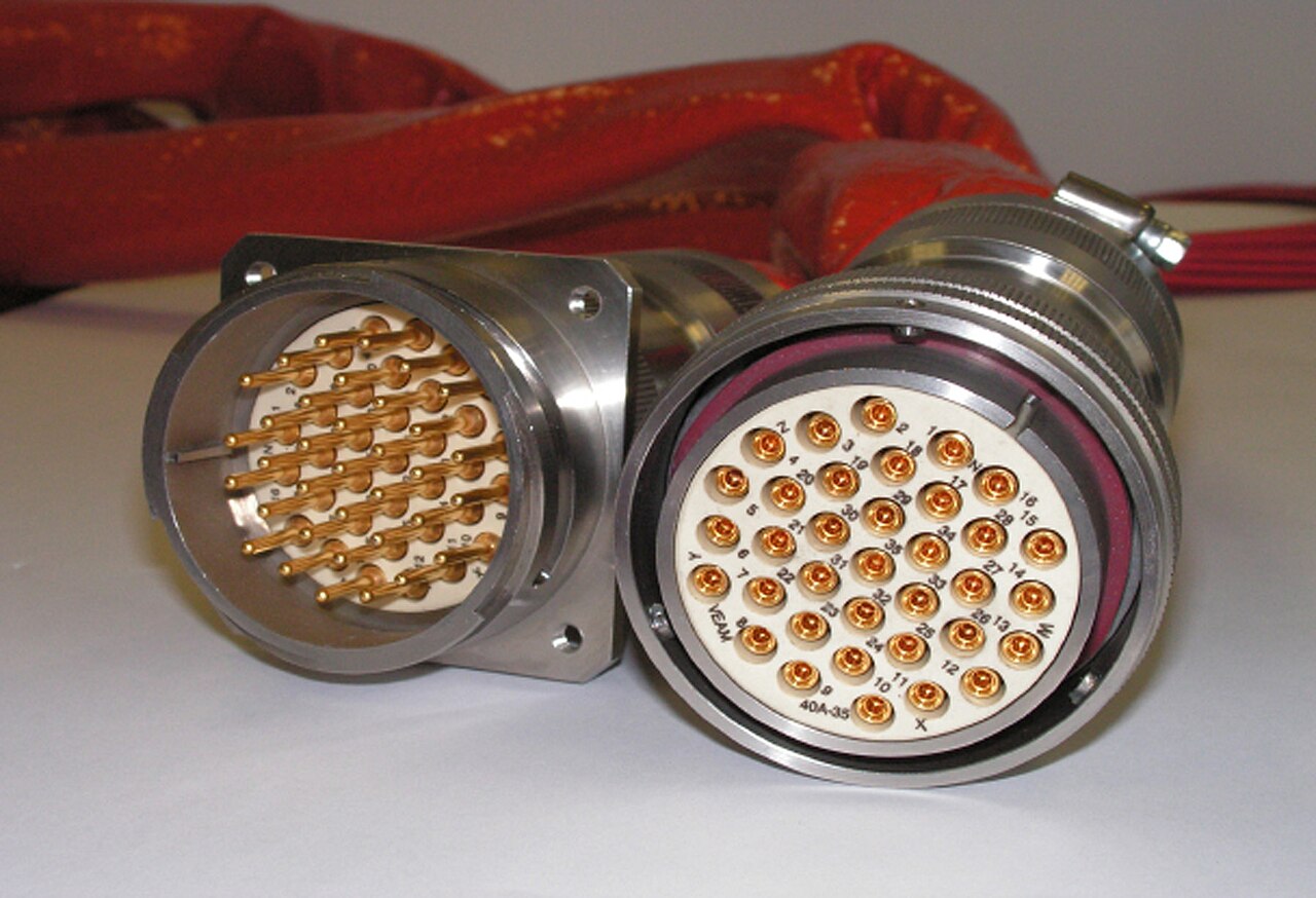
The circular category in the flesh: a square-flange receptacle and its cable plug (ITT Cannon/VEAM CIR-series, 35-way) — gold crimp contacts, coupling ring, panel-mount flange. Photo: ITT Cannon, public domain, via Wikimedia Commons.
Board-to-wire connectors like Molex Micro-Fit, Mini-Fit, Mega-Fit, and sealed Squba are not "hobby" parts. Professional versions have positive latches, polarization, secondary locks (TPA — Terminal Position Assurance, a secondary lock that confirms every contact is fully seated before the connector can mate), and defined current/voltage ratings — and some family members (like sealed Squba) add environmental sealing while their siblings (like Micro-Fit itself) have none. The dividing line is the specific family and rating, not the brand.
Fiber connectors — a brief orientation
The category table lists fiber for completeness, but optical connectors are their own discipline, and this guide keeps them at orientation level:
- Datacom / indoor: LC and SC dominate structured cabling and equipment — ceramic ferrules, polished endfaces, clean-before-mate discipline.
- Rugged / military: expanded-beam connectors (including expanded-beam MIL-DTL-38999 variants) tolerate dust and vibration better than physical-contact ferrules; ARINC 801 termini and MIL-DTL-38999 fiber slash sheets place optical contacts into the same rugged circular shells used for copper.
- What drives selection: endface cleanliness, alignment/insertion loss, bend radius, and single- vs. multi-mode — not the mechanical envelope.
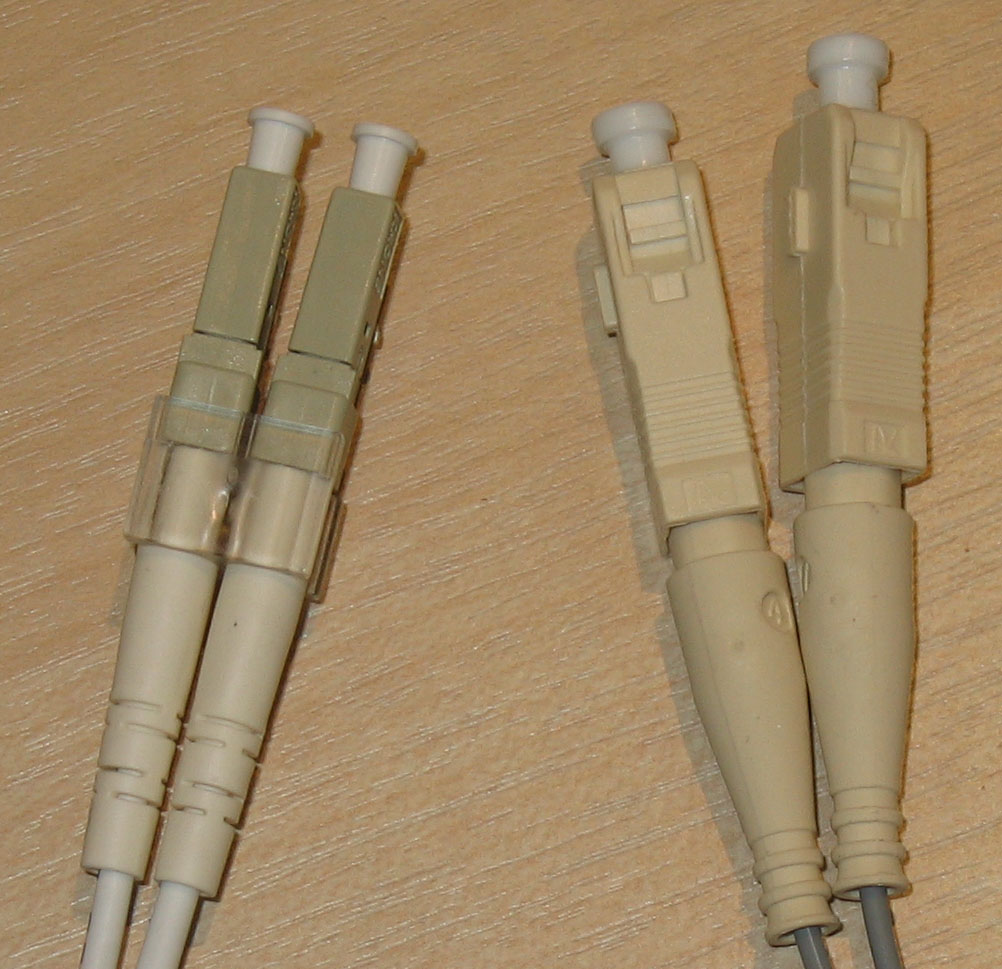
Datacom fiber families at recognizable scale: duplex LC on the left and SC on the right. The white caps protect the polished ferrule endfaces—the surface whose cleanliness and condition directly affect the optical link. Photo: Poil, CC BY-SA 3.0, via Wikimedia Commons.
Fiber connector performance depends heavily on cleanliness, inspection, polish/interface type, bend radius, transceiver requirements, and installation process. Do not select fiber connectors by shape alone.
Minimum fiber connector decision fields — capture these before choosing (they are decision-support fields, not ratings):
| Field | Record |
|---|---|
| Fiber type | single-mode / multimode |
| Connector family | LC / SC / expanded-beam / MIL-DTL-38999 fiber termini / other |
| Polish type (if physical-contact) | per the interface specification |
| Insertion loss budget | dB, from the link budget |
| Return loss requirement | dB, per interface/transceiver |
| Wavelength | per transceiver |
| Transceiver / interface | exact module and its connector requirement |
| Cleaning / inspection requirement | process + scope/inspection equipment |
| Dust cap requirement | caps on every unmated port |
| Bend radius | cable and boot minimums |
| Strain relief | boot/backshell strategy |
| Environmental sealing | rating + test condition, if external |
| Expanded-beam vs. physical-contact rationale | dust/vibration tolerance vs. loss trade |
| Test method | how loss/return loss will be verified |
| Fiber owner / reviewer | who signs off |
| Source document / datasheet | identifier + revision/date |
A full fiber deep-dive is out of scope for v1 of this guide; treat this as a pointer and work from the connector/fiber manufacturer and the applicable standard.
RF connectors — a brief orientation
The category table lists RF/coax for completeness; like fiber, RF connectors are their own discipline, and this guide keeps them at orientation level:
- Impedance is a system property: the connector, cable, and terminations form a controlled-impedance line — 50 Ω dominates RF/microwave, GPS, and comms; 75 Ω dominates video/broadcast. The two don't mix, and visually similar connectors (BNC exists in both) are not interchangeable.
- Families have frequency ceilings: as a rough ordering, SMA-class connectors reach higher frequencies than N/TNC, which reach higher than BNC — but the exact ceiling is a datasheet parameter for the specific connector and cable, not a family constant.
- Mating torque is a specification, not a feel: threaded RF interfaces (SMA and kin) specify a mating torque — use the torque wrench; over- or under-torquing degrades the match and damages mating interfaces.
- Protect high-cycle test ports: use a sacrificial adapter (a "connector saver") on ports that see many mate cycles, so the wear lands on the cheap replaceable part.
RF connector selection is not only mechanical fit. Frequency range, impedance control, launch geometry, cable assembly quality, bend radius, torque, return loss, insertion loss, and environmental sealing can dominate performance.
Before choosing, capture at minimum: signal/function, frequency range, characteristic impedance, connector family, cable type, insertion-loss budget, return-loss/VSWR requirement, power at frequency, environmental sealing, mate-cycle expectation, torque requirement, vibration/strain relief, whether a connector saver is required, the test-equipment interface, the RF owner/reviewer, and the source document/datasheet — the RF decision path carries this as a fill-in table.
A full RF deep-dive is out of scope for v1 of this guide; treat this as a pointer and work from the connector/cable manufacturer's data and your RF requirements.